eng eng
8. Actual test pressure (p actual) is adjusted to reference test pressure (p
refer) \ Enter
9. Stabilisation/wait time (t stabi) running, actual test pressure (p actual) is
changed to reference test pressure (p refer) on expiring. The stabilisation/
wait time can be ended prematurely with Enter, test time (t test) \ Enter (\
Esc = cancel).
10. Display screen: Reference test pressure (p refer), actual test pressure (p
actual), differential test pressure (p diff), test time (t test) \ Enter
11. Esc >> Start menu \ Memory Manager, data transfer >> 3.6
3.4.3. Pressure test with water, testmethodPfS(B/2): Press connections
unpressed leaking (information leaet "Leak tests of drinking water installations
with compressed air, inert gas or water" (January 2011) of the German Central
Association for Sanitary, Heating and Air Conditioning (ZVSHK), supplement
to EN 806-4:2010, 6.1.3.2,)
Program sequence ↑ ↓ (8):
1. Test \ Enter
2. Test with water \ Enter
3. Test with water B \ Enter
4. Test PfS (B/2) \ Enter
5. Check reference test pressure default (p refer) and change if necessary
(11) \ ↓
6. Check test time default (t test) and change if necessary (11) \ ↓
7. Actual test pressure (p actual) is adjusted to reference test pressure (p
refer) \ Enter, test time (t test) begins immediately (\ Esc = cancel)
8. Display screen: Reference test pressure (p refer), actual test pressure (p
actual), differential test pressure (p diff), test time (t test) \ Enter
9. Esc >> Start menu \ Memory Manager, data transfer >> 3.6
3.4.4. Pressure test with water, testmethodP+M(B/3): Plastic and metal pipe
systems (EN 806-4:2010, 6.1.3.3 and information leaet "Leak tests of drinking
water installations with compressed air, inert gas or water" (January 2011) of
the German Central Association for Sanitary, Heating and Air Conditioning
(ZVSHK).
Program sequence ↑ ↓ (8):
1. Test \ Enter
2. Test with water \ Enter
3. Test with water B \ Enter
4. Test P+M(B/3) \ Enter
5. Check reference test pressure default (p1 refer) and change if necessary
(11) \ ↓
6. Check reference test pressure default (p2 refer) and change if necessary
(11) \ ↓
7. Check test time default (t1 test) and change if necessary (11) \ ↓
8. Check test time default (t2 test) and change if necessary (11) \ ↓
9. Actual test pressure (p1 actual) is adjusted to reference test pressure (p1
refer) \ Enter, test time (t1 test) begins immediately (\ Esc = cancel)
10. Actual test pressure (p2 actual) is adjusted to reference test pressure (p2
refer) \ Enter, test time (t2 test) begins immediately (\ Esc = cancel)
11. Display screen: Reference test pressure (p1 refer), actual test pressure
(p1 actual), differential test pressure (p1 diff), test time (t1 test)
Reference test pressure (p2 refer), actual test pressure (p2 actual), differ
-
ential test pressure (p2 diff), test time (t2 test) \ Enter
12. Esc >> Start menu \ Memory Manager, data transfer >> 3.6
3.4.5. Pressure test with water, test method C (EN 806-4:2010, 6.1.3.4)
Program sequence ↑ ↓ (8):
1. Test \ Enter
2. Test with water \ Enter
3. Test with water C \ Enter
4. Check reference test pressure default (p refer) and change if necessary
(11) \ ↓
5. Check stabilisation default (t0 stabi) and change if necessary (11) \ ↓
6. Check test time default (t1 test) and change if necessary (11) \ ↓
7. Check test time default (t2 test) and change if necessary (11) \ Enter
8. Actual test pressure (p0 actual) is adjusted to reference test pressure (p
refer) \ Enter
9. Stabilisation/wait time (t stabi) running, actual test pressure (p actual) is
changed to reference test pressure (p refer) on expiring. The stabilisation/
wait time can be ended prematurely with Enter, the test time (t1 test) begins
immediately followed by test time (t2 test) (\ Esc = cancel).
10. Display screen: Reference test pressure (p refer), actual test pressure (p0
actual), differential test pressure (p0 diff), test time (t0 test)
Actual test pressure (p1 actual), differential test pressure (p1 diff), test time
(t1 test) actual test pressure (p2 actual), differential test pressure (p2 diff),
test time (t2 test) \ Enter
11. Esc >> Start menu \ Memory Manager, data transfer >> 3.6
3.5.Cleaningandpreservationofheatingsystems
Before cleaning and preserving heating systems with REMS Multi-Push, safety
devices for the prevention of drinking water contamination by owback, e.g.
pipe network separator BA in accordance with EN 1717:2000 must be installed
to protect the drinking water against contamination.. Never allow cleaner or
corrosion protection agent to ow though the pipes of REMS Multi-Push.
The cleaning and preservation procedure is as follows:
●
The heating system to be cleaned is ushed with a water/air mixture with
intermittent compressed air (see 3.1.2.). This reinforces the subsequent
cleaning. Pay attention to possible pressure limiting of the heating system!
●
Empty the heating system after ushing.
●
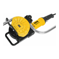
Connect the cleaning and preservation unit REMS V-Jet H (Fig. 7), as
described under 2.7.
●
Screw a 1 l bottle of REMS CleanH, cleaner for heating systems, to the
REMS V-Jet H cleaning and preservation unit (Fig. 7).
●
Program 3.1.1. Select ush with water (without air supply). A drain must
be opened at the end of the heating system to be cleaned during the lling
process. This must stay open until the green coloured cleaning solution
ows out from there.
●
The bottle may have to be changed to clean heating systems with > approx.
100 l . To do this, close the supply and drain and remove the bottle (21)
slowly so that excess pressure can escape.
●
The cleaning solution must be drained from the heating pipes again after
an application time of approx. 1 hour.
After cleaning, the heating system is relled with the addition of REMS
NoCor corrosion protection for preservation of heating systems until the
blue coloured corrosion protection solution emerges. The bottle is tted
and changed as described above. The corrosion protection solution then
remains permanently in the heating system.
Attention:Therespectivenationalsafetyprovisions,rulesandregu
-
lations valid for the application site as well as the regulations of the
hotwaterboilermanufacturermustbeconsideredandobserved.
●
Flush/clean the REMS V-Jet H thoroughly with clean water at the end of
work.
3.6.Compressedairpumpprogram
The pressure is displayed and controlled to the reference test pressure (p refer)
selected on the screen in the range from 200 to 0 descending in hPa (mbar,
psi) and in the range from 0.2 to 8.0 ascending in MPa (bar, psi).
Program sequence ↑ ↓ (8):
1. Compressed air pump \ Enter
2. Check reference test pressure default (p refer) and change if necessary
(11) \ Enter
3. The vessel is pumped up to the reference test pressure (p refer).
4. Esc >> Start menu \ Memory Manager, data transfer >> 3.6
The pressure of a vessel that is already under pressure is specied as p actual
after connecting the vessel.
The program can be aborted at any time with the Esc button (10). Then all the
valves open and the pressure is released. The pump-up is saved but "Cancel"
is shown in the le.
3.7. MemoryManager,datatransfer,logging
Four functions are provided for memory management:
●
Display saved results of the ushing and testing programs
●
Print saved results of the ushing and test programs on a printer. Plug the
USB lead (Fig. 9 (42)) into the USB port (Fig. 2 (33)).
●
Delete saved results of the ushing and testing programs
●
Save results of the ushing and test programs on a USB stick. Plug in the
USB stick at the USB port (Fig. 2 (33)).
Display / Pressure
Delete le no.
Delete all les
Save USB
Customer:
REMS Multi-Push
Date: 28.05.2014
Hour: 13 :22
File-No. 000051
Test with water A
p prefer bar 11.3
p actual bar 11.3
p diff bar 0.0
t test min 002 : 00
Tester:
The results of the ushing and test programs are saved with date, time and log
number in the selected language and can be transferred to a USB stick or
printer (accessory part no. 115604) (neither of which is included in the scope
of supply) for documentation. Necessary additions to saved data, e.g. customer
name, project number, tester, are possible on external devices (e.g. PC, laptop,
tablet PC, smartphone). Paper roll, pack of 5, for printer (Art. No. 090015).
Insert the paper roll and charge the battery before using the printer (Fig. 9 (40)).
If the printer is charged without the paper roll inserted, the LED (41) ashes
repeatedly 3 times. Push back the paper compartment rail (42) to open the
paper roll compartment. Insert the paper roll so that its end is transported from
below. Close the paper compartment. Keep the button (43) pressed for manual
paper feed. Connect the charger (44) and USB lead (45) to the printer and
charge the printer. To print stored results of the ushing and test programs,
plug the USB lead (45) into the USB port (Fig. 2 (33)). After selecting the memory
manager, press Enter, the printer switches on automatically. Select the Display/
Print menu item, select the le no. Press Enter to print the data shown on the
screen. Press the the button (43) twice to switch off the pusher. The connection
to the USB line (45) or charger (44) must be disconnected. The following printer
functions are indicated with the LED (41).
24