LED ashes repeatedly once: printer ready for operation.
LED ashes repeatedly twice: overheating
LED ashes repeatedly 3 times: low paper
LED ashes repeatedly 4 times: unsuitable charger
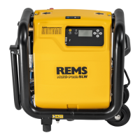
3.8. Operationofcompressedairtools
Compressed air tools can be operated up to a max. air requirement of 230 Nl/
min can be operated directly from the compressed air vessel. The air pressure
supplied by the compressed air vessel can be checked on the compressed air
vessel pressure gauge (Fig. 4 (30)). The compressor can be switched off at
any time with the compressor emergency stop button (Fig. 4 (29)). The adjusting
wheel must be raised to set the pressure of compressed air tools (Fig. 4 (31)).
The set pressure can be read at the compressed air tools pressure gauge (Fig.
4 (32)).
3.9. Transport and storage
Drain REMS Multi-Push, REMS V-Jet TW, REMS V-Jet H as well as all hoses
completely to avoid damage; store dry at ≥ 5°C. Residue water from pressure
testing with water, ushing, disinfection, cleaning and preservation should be
removed with the connecting hose compressor/water connections (Fig. 8 (38))
after every use. This is connected to the compressed air tools connection on
one side (Fig. 4 (28)) and respectively to the ushing supply (Fig. 1 (14)) or the
pressure test with water supply on the other side (Fig. 1 (24)). See 3.7 for the
further procedure.
Protect REMS Peroxi Color, REMS CleanH and REMS NoCor against frost,
heat and direct sunlight. Keep containers tightly closed and store in a cool,
well-aired place.
The water connections on the device and the hoses should be sealed by caps
or plugs to prevent contamination.
4. Maintenance
4.1. Inspection
WARNING
Pulloutthemainsplugbeforeinspection!
Check hoses and seals for damage before every use. Replace damaged hoses
and seals. Keep all the hose connections clean. Remove water residue from
ushing, disinfection, cleaning, preservation or from the pressure test with water
with the compressor/water connections connecting hose (Fig. 8 (38)) after every
use. Seal machine connections and hose ends with caps or plugs. Flush the
REMS V-Jet TW disinfection unit or REMS V-Jet H cleaning and preservation
unit (Fig. 7), without bottle (Fig. 7 (21)), with fresh water after every use.
Keep all the hose connections clean. Open both condensation screw plugs
from time to time (Fig. 1 (34)) to drain condensation from the compressed air
tank (Fig. 1 (35)), especially necessary when working at low temperatures;
observe storage temperature for unit of ≥ 5°C (1.3).
Remove the protective hood for the following maintenance work. Loosen the
6 screws of the protective hood (Fig. 1 (37)). Empty the tank of the condensa-
tion and particle lter in the electronic ushing and pressure testing unit with
compressor regularly. The lter cartridge must be cleaned and replaced if
necessary. Clean the air lter of the compressor regularly.
Change the ne lter cartridge (Art. No. 043054) of the ne lter (Art. No.
115609) regularly.
It is not necessary to calibrate the control elements of the REMS Multi-Push.
It is recommended to check the pressure gauge every 2 years. The applied
pressures can be checked if necessary by additionally connecting a suitable
pressure gauge (see Accessories 1.2).
In order to ensure that the date and time remain saved at all times, the button
cell (Lithium CR1220, 3 V) on the back of the operating panel (Fig. 1 (36))
should be changed about every two years. Loosen the 6 screws of the protec
-
tive hood (Fig. 1 (37)) to do this, remove the protective hood. Then loosen the
4 screws of the operating panel and change the button cell on the back of the
operating panel.
Clean the machine regularly especially when it has not been in use for a long
time. Clean plastic parts (e.g. housing) only with REMS CleanM machine cleaner
(Art. No. 140119) or a mild soap and a damp cloth. Do not use household
cleaners. These often contain chemicals which can damage the plastic parts.
Never use petrol, turpentine, thinner or similar products for cleaning.
Make sure that liquids cannot get inside the electronic ushing and pressure
testing unit with compressor.
4.2. Inspection / Repair
WARNING
Pulloutthemainsplugbeforecarryingoutmaintenanceorrepairwork!
This work may only be performed by qualied personnel.
eng eng
5. Fault
NOTICE
If faults occur, rst check whether the respective latest version software (Ver. Software) is installed on the input and control unit. Select the Settings menu and then
Device data to display the version software. The latest version software (Ver. Software) for the input and control unit is available by USB stick as a download under
www.rems.de → Downloads → Software. Compare the number of the version software with the latest version software number and install the latest version software
on the input and control unit by means of a USB stick if necessary. See 2.3 for the further procedure.
If the REMS Multi-Push welcome message remains constant in the control panel or if the Error message is displayed in any program on the control panel (36), the
power supply of REMS Multi-Push should be interrupted by pulling out the mains plug or pressing the RESET button and switched back on according to 2.1.
Electrical Connection. If Error is displayed again, the procedure must be repeated after pressure in the REMS Multi-Push has been relieved. To do this, pull out
the mains plug, close the water pipe and remove all the hoses, caps and stoppers from the REMS Multi-Push, then switch back on according to 2.1. Electrical
Connection of Machine.
5.1. Fault: Electronic ushing and pressure testing unit with compressor does not switch on after pressing the On/Off button (4).
Cause: Remedy:
●
On/Off button (Fig. 2 (4)) pressed too briey.
●
Press On/Off button for about 2 s, then release.
●
PRCD fault current circuit breaker (Fig. 1 (1)) is not switched on.
●
Switch on PRCD fault current circuit breaker as described in 2.1..
●
Mains lead/PRCD defective.
●
Have the mains lead/PRCD changed by qualied personnel or an authorised
REMS customer service workshop.
●
Electronic ushing and pressure testing unit with compressor defective.
●
Have the electronic ushing and pressure testing unit with compressor
checked/repaired by an authorised REMS customer service workshop.
5.2. Fault: Compressor will not start although there is low or no pressure in the compressed air tank (see the display on the compressed air tank pressure gauge
(Fig.4 (30)).
Cause: Remedy:
●
Compressor emergency stop button (Fig.4 (29)) is switched off.
●
Switch on compressor by pulling out the emergency stop button.
●
Electronic ushing and pressure testing unit with compressor defective.
●
Have the electronic ushing and pressure testing unit with compressor
checked/repaired by an authorised REMS customer service workshop.
5.3. Fault: The necessary minimum ow velocity is not achieved in the ushing program.
Cause: Remedy:
●
Stop tap of the house connection is only partly open.
●
Fully open the stop tap.
●
Fine lter (Fig. 3 (12)) is contaminated.
●
Clean or change the ne lter and lter cartridge.
●
Not enough tapping points opened.
●
Open the appropriate number of tapping points.
●
Hoses connected incorrectly.
●
Connect hoses as shown in Fig. 3.
●
Wrong defaults entered.
●
Check defaults, correct if necessary. Restart the program.
●
Valves blocked, considerable, irremovable encrustations in the pipes.
●
Clean/change valve(s). Clear encrustations.
25