6-30 Electrical Data Rexroth IndraDrive M
DOK-INDRV*-HMS+HMD****-PR04-EN-P
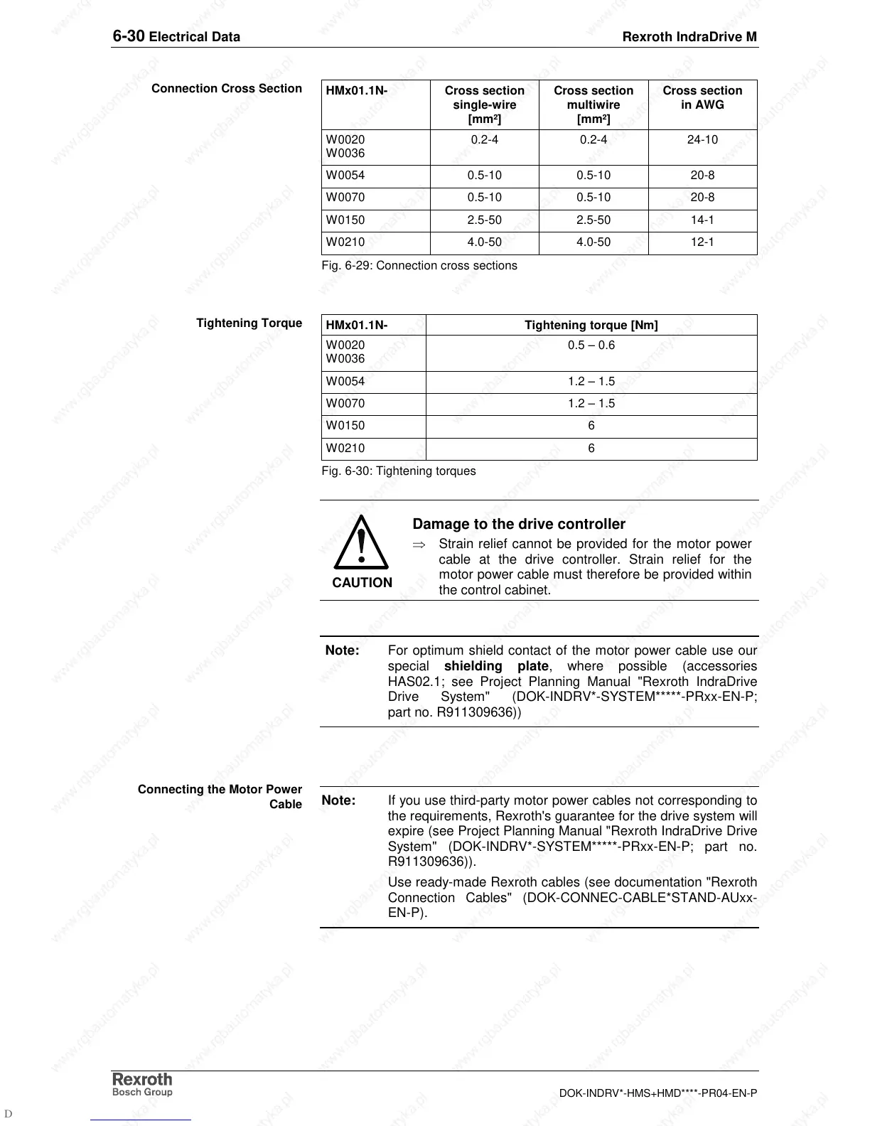
HMx01.1N- Cross section
single-wire
[mm²]
Cross section
multiwire
[mm²]
Cross section
in AWG
W0020
W0036
0.2-4 0.2-4 24-10
W0054 0.5-10 0.5-10 20-8
W0070 0.5-10 0.5-10 20-8
W0150 2.5-50 2.5-50 14-1
W0210 4.0-50 4.0-50 12-1
Fig. 6-29: Connection cross sections
HMx01.1N- Tightening torque [Nm]
W0020
W0036
0.5 – 0.6
W0054 1.2 – 1.5
W0070 1.2 – 1.5
W0150 6
W0210 6
Fig. 6-30: Tightening torques
CAUTION
Damage to the drive controller
⇒
Strain relief cannot be provided for the motor power
cable at the drive controller. Strain relief for the
motor power cable must therefore be provided within
the control cabinet.
Note: For optimum shield contact of the motor power cable use our
special shielding plate, where possible (accessories
HAS02.1; see Project Planning Manual "Rexroth IndraDrive
Drive System" (DOK-INDRV*-SYSTEM*****-PRxx-EN-P;
part no. R911309636))
Note: If you use third-party motor power cables not corresponding to
the requirements, Rexroth's guarantee for the drive system will
expire (see Project Planning Manual "Rexroth IndraDrive Drive
System" (DOK-INDRV*-SYSTEM*****-PRxx-EN-P; part no.
R911309636)).
Use ready-made Rexroth cables (see documentation "Rexroth
Connection Cables" (DOK-CONNEC-CABLE*STAND-AUxx-
EN-P).
Connection Cross Section
Tightening Torque
Connecting the Motor Power
Cable