Rexroth IndraDrive M Electrical Data 6-19
DOK-INDRV*-HMS+HMD****-PR04-EN-P
6.4 Control Voltage
Note: The data below apply to the power sections.
The data refer to an ambient temperature of 25 °C.
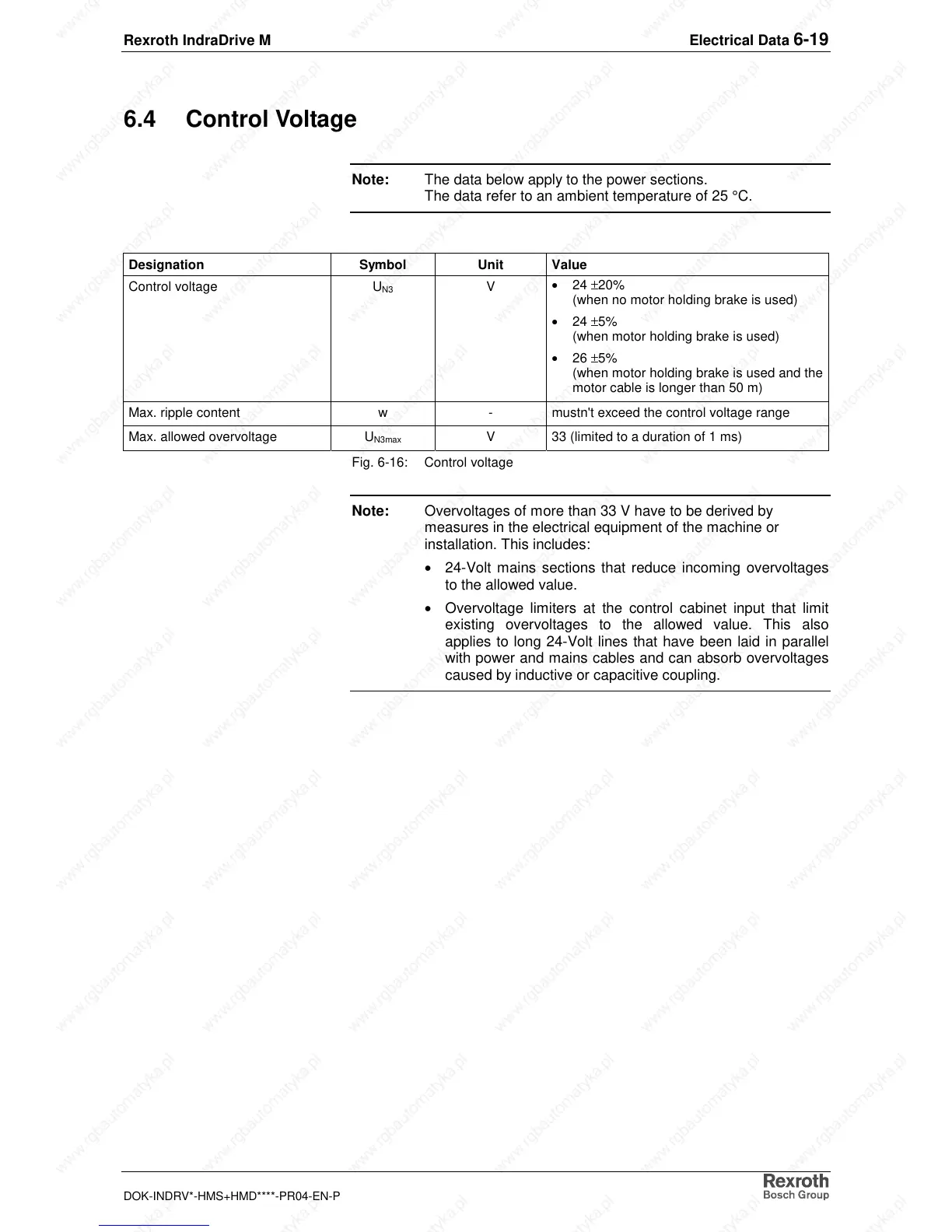
Designation Symbol Unit Value
Control voltage U
N3
V
• 24 ±20%
(when no motor holding brake is used)
• 24 ±5%
(when motor holding brake is used)
• 26 ±5%
(when motor holding brake is used and the
motor cable is longer than 50 m)
Max. ripple content w - mustn't exceed the control voltage range
Max. allowed overvoltage U
N3max
V 33 (limited to a duration of 1 ms)
Fig. 6-16: Control voltage
Note: Overvoltages of more than 33 V have to be derived by
measures in the electrical equipment of the machine or
installation. This includes:
• 24-Volt mains sections that reduce incoming overvoltages
to the allowed value.
• Overvoltage limiters at the control cabinet input that limit
existing overvoltages to the allowed value. This also
applies to long 24-Volt lines that have been laid in parallel
with power and mains cables and can absorb overvoltages
caused by inductive or capacitive coupling.