ASMxxxx Series User’s Manual
Asia Pacific | EMEA | Americas 154
ASM/CAM/SAM/RSM DC Power connector (Phoenix 2-pin) pin-out:
The pin numbers on the polarized Phoenix 2-pin connector on the rear of the ASM (and optional CAM) are illustrated below.
Pinout of DC Connector
Pin Function Table:
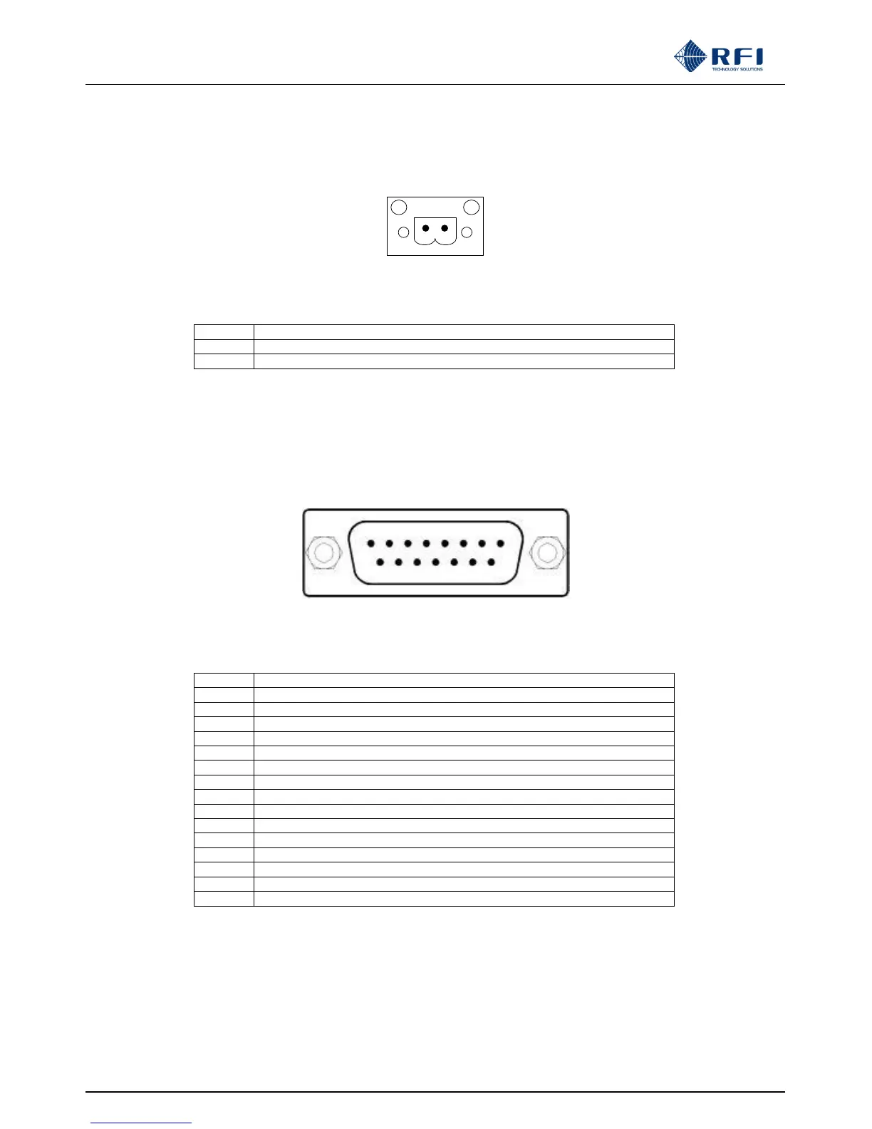
ASM Alarm/Comms connector (Sub D DB-15) pin-out:
The pin numbers on the DB15 (M) at the rear of the ASM are illustrated below.
An electrical schematic of the alarm pin-outs to the D-Sub DB15 (M) connector located at the rear of the ASM is illustrated on
the next page.
Pinout of DB15 Connector
Pin Function Table:
Communications Buss - GND
ASM Alarm Relay #3 – Closed when an alarm is present
ASM Alarm Relay #2 – Open when an alarm is present
ASM Alarm Relay #2 – Common
ASM Alarm Relay #4 – Closed when alarm is present
ASM Alarm Relay #1 – Open when an alarm is present
ASM Alarm Relay #1 – Common
ASM Alarm Relay #3 – Open when an alarm is present
ASM Alarm Relay #3 – Common
ASM Alarm Relay #2 – Closed when an alarm is present
ASM Alarm Relay #4 – Open when an alarm is present
ASM Alarm Relay #4 – Common
ASM Alarm Relay #1 – Closed when an alarm is present