ASMxxxx Series User’s Manual
Asia Pacific | EMEA | Americas 155
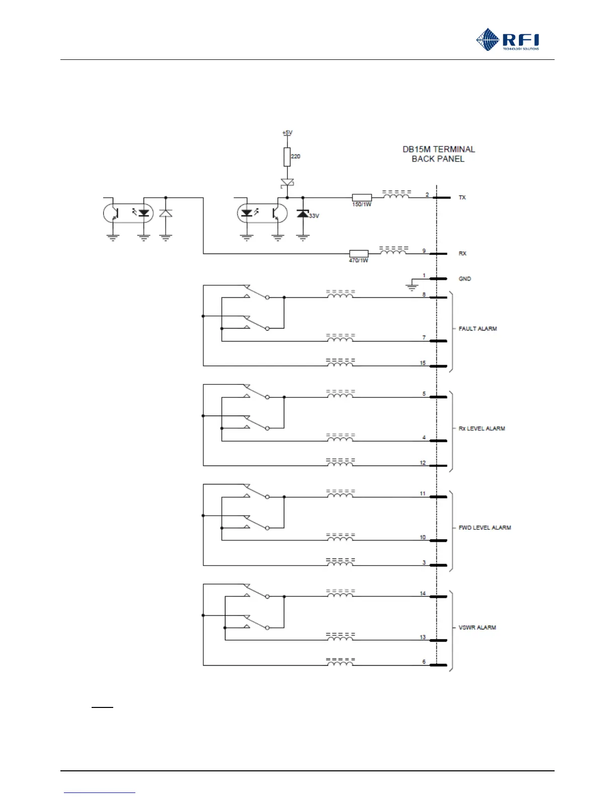
ASM Alarm/Comms connector (Sub D DB-15) pin-out Electrical Schematic:
Note: The ASM alarm relay outputs may be assigned to individual channel, Network ID group, or summary alarms
(summary alarm names shown in above diagram)