3.Replacement
71
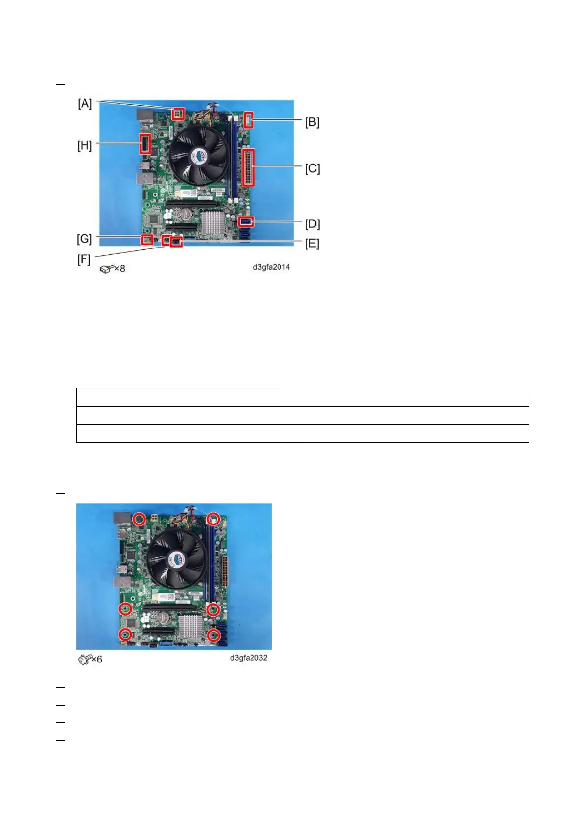
2. Remove the cables from the motherboard.
4-pin power connector: PWRCONN1 [A].
Top chassis fan cable connector: FRONT FAN [B].
24-pin power connector: PWR [C].
SATA data cable connector: SATA0 [D].
USB cable: J13 [E].
Front panel connector: J11 [F].
Bottom chassis fan cable connector: REAR FAN [G].
DIAG connector: EFI GPIO Header [H].
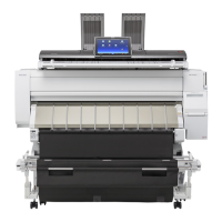
3. Remove the Motherboard.
4. Remove the Memory [Link to Memory – 4 GB DIMM (E-25C)]
5. Remove the CPU Cooling Assembly [Link to CPU and Cooling Assembly]
6. Remove the CPU [Link to CPU and Cooling Assembly]
7. Remove the Keychip [A] from socket J23 on the old motherboard.
Pull the chip straight out of the socket. Make sure not to put stress on surrounding components.