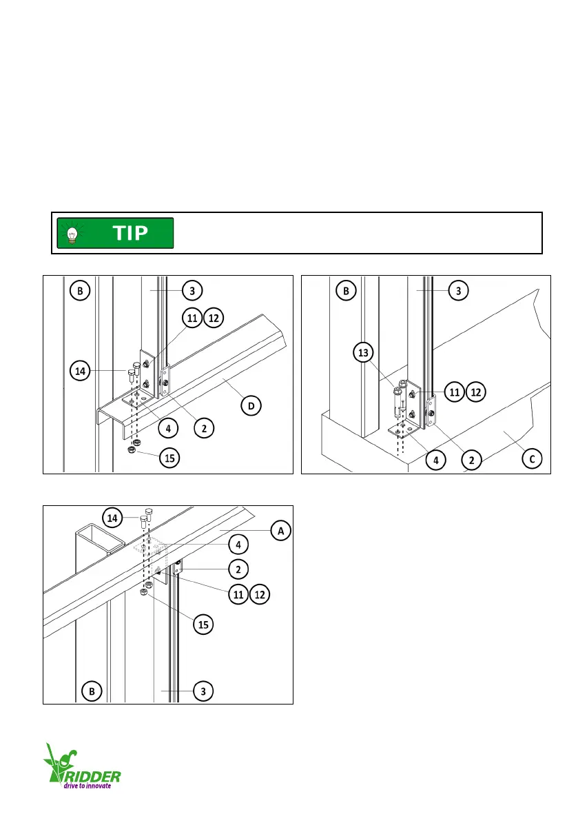
Install the guiding prole (3) with guiding unit (2)
1. - Aach the mounng bracket (4) with bolts M8 (14) (2x or 3x) and self-locking nuts (15) to the
purlin (D). Refer to illustraon 4.3.8
OR
- Aach the mounng bracket (4) with anchor bolts M8 (13) (2x or 3x) to the foundaon (C).
Refer to illustraon 4.3.9.
2. Aach the mounng bracket (4) with bolts M8 (14) (2x or 3x) and self-locking nuts (15) to the
purlin (A). Refer to illustraon 4.3.10.
3. Fully ghten the 4 bolts M6 (11) and self-locking nuts (12) of the mounng brackets (4).
Refer to illustraons 4.3.8/4.3.9/4.3.10.
Make sure that the guiding unit (2) is put onto the guiding prole (3)
before installaon. REFER TO ILLUSTRATION 4.3.2.
This prevents more subsequent work.
4.3.8 4.3.9
4.3.10
Ridder Drive Systems
T +31 (0)341 416 854 F +31 (0)341 416 611 I www.ridder.com
15