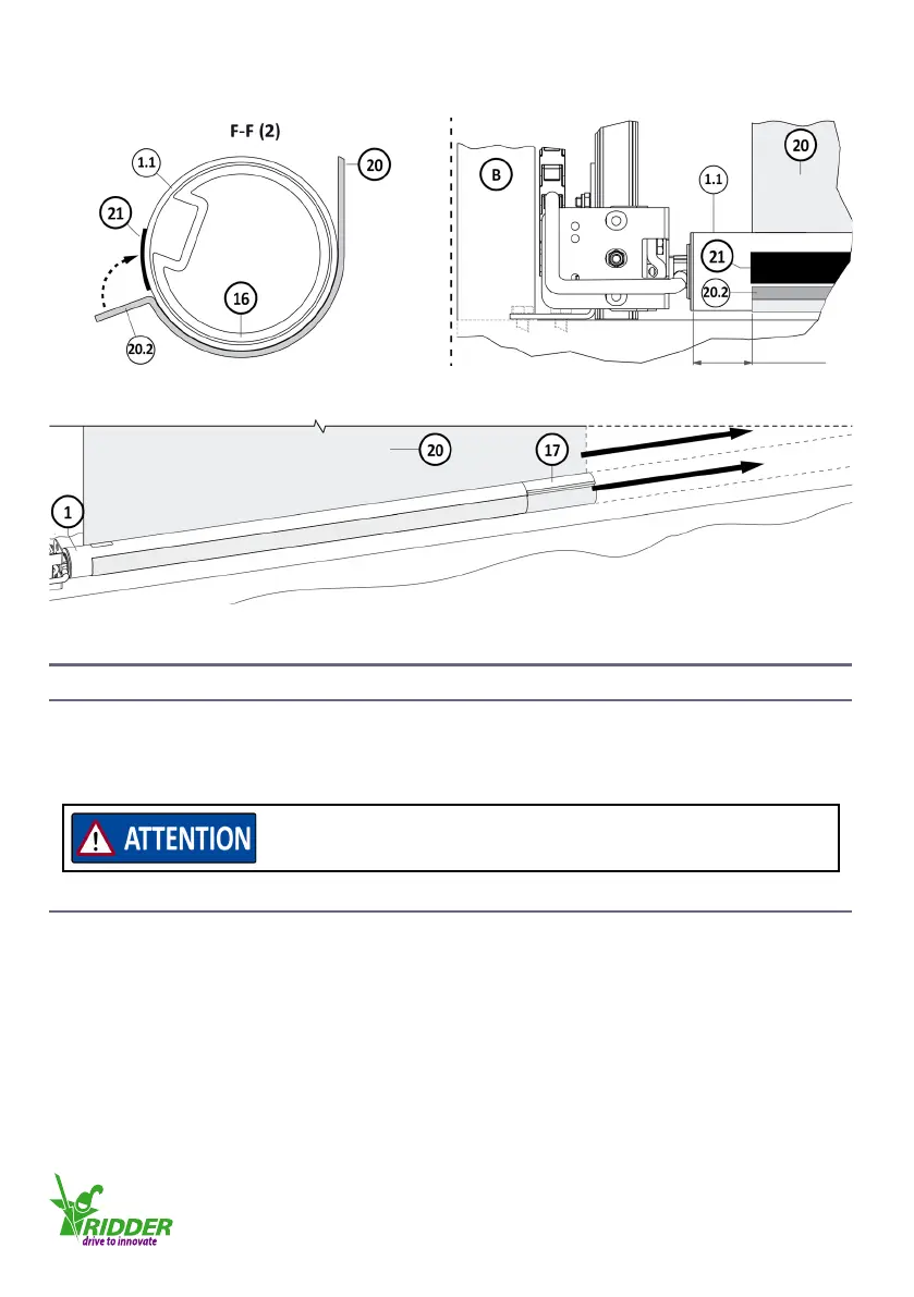
10. Aach the screen cloth (20.2) onto the tube (1.1) with double-sided adhesive tape (21). Refer to
illustraons 4.7.1/4.7.6/4.7.7.
11. Pull the screen cloth (20) ght along the full length. Make sure that it does not fold!
5. CONNECT INSTRUCTIONS
5.1 Electrical material
• A minimum conductor diameter of 1.5 mm² is applicable to the cables in the wiring diagrams. For
the used components, electrical material and cable lengths the necessary conductor diameter can
be dierent.
5.2 Protecon - Condions and starng points
The condions that follow are applicable to the wiring diagrams.
• The installer makes sure that a motor-protecon circuit-breaker (MPCB) and other necessary
protecons are used.
• The installer must include not shown protecons in the wiring diagrams.
• Do not connect other electrical equipment (lamps, relays and such) directly to the connecon
cables of the motor.
• Isolate all poles, with a minimum contact separaon of 3 mm per pole (EN 60335), from the
mains voltage.
40 mm
4.7.6 4.7.7
Use only applicable components and electrical material.
Always refer to the related informaon and manuals.
Ridder Drive Systems
T +31 (0)341 416 854 F +31 (0)341 416 611 I www.ridder.com
22