Do the procedure that follows.
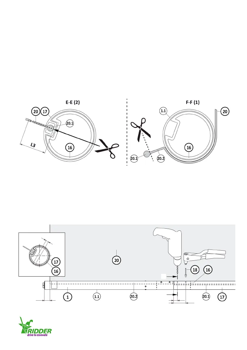
1. Pull the cord (20.1 of the screen cloth) through the groove, in the direcon of the end (on the
coupling piece) of the winding tube (17). Refer to illustraon 4.7.3.
2. Connue to pull the cord (20.1) unl the distance, from the end of the winding tube (17), is
equal to l2 (l minus 40 mm).
Note: Keep the minimum distance of 40 mm free between the screen cloth (20) and the head of
the tube motor. This makes sure the guiding system can move freely during wind up if the screen
cloth is not cut straight. Refer to illustraons 4.7.1/4.7.5
3. Cut along the cung line (l3) at the distance of L2 from the end of the screen cloth (20). Make
an esmate of the length of l3. Refer to illustraons 4.7.1/4.7.3.
4. Cut and discard the cord (20.1) along the distance of L2 of the screen cloth (20.2). Refer to
illustraons 4.7.1/4.7.4.
5. Make sure that the winding tube (17) is put against the tube (1.1). For the four recommended
drilling posions (d) in the winding tube (17) and the coupling piece (16) refer to illustraons
4.7.5/G-G.
6. Drill one of the holes for the pop-rivets (18) into the winding tube (17) and coupling piece (16)
(minimum of ø5.2 mm if pop-rivets of ø5 mm are used).
7. Use a pop-rivet pliers to aach the pop-rivet (18).
8. Drill the holes for the other three pop-rivets (18).
9. Use the pop-rivet pliers to aach the other three pop-rivets (18).
4.7.3 4.7.4
4.7.5
G-G
d (4x)
25
75
G
G
40
Ridder Drive Systems
T +31 (0)341 416 854 F +31 (0)341 416 611 I www.ridder.com
21