7.2 Special tools and equipment
Adjusng switch RB50Eᵖˡᵘˢ tube motor
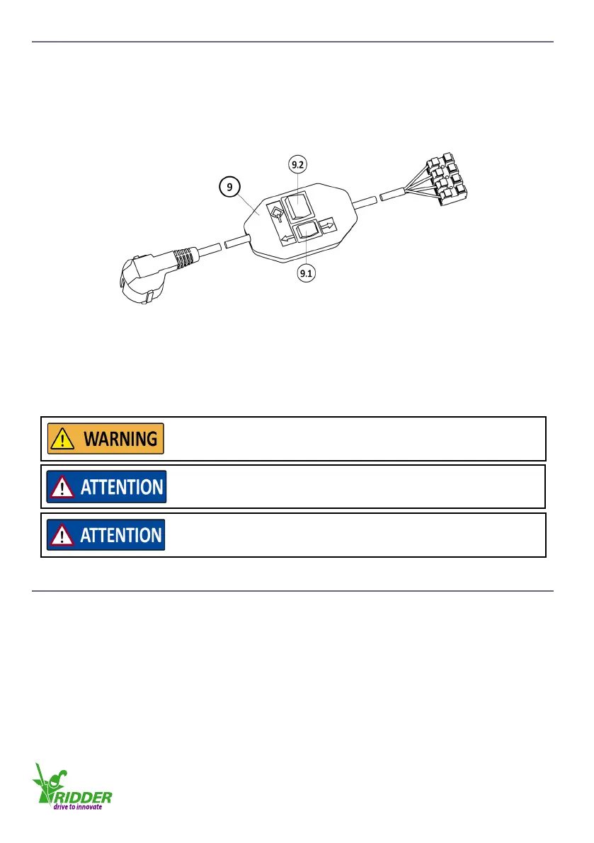
For the commissioning of an RB50Eᵖˡᵘˢ tube motor the “Adjusng switch RB50Eᵖˡᵘˢ” is necessary.
The adjusng switch (9) for the RB50Eᵖˡᵘˢ tube motor is only used:
• To set the limit-switch system
• Drive the tube motor during installaon, maintenance or service.
Connect the tube motor, for the “operang mode”, always to the control box again.
Buons of the adjusng switch:
• 9.1 Up-Down buon
• 9.2 Programming buon.
Connect the adjusng switch to the tube motor
Connect the wires from the tube motor “colour to colour” to the connecon block on the adjusng
switch. Note: If the connecon is incorrect it is not possible to set the tube motor (again).
7.3 RB50Eᵖˡᵘˢ limit-switch system
The RB50Eᵖˡᵘˢ tube motor has an electronic limit-switch system with a pulse counter.
The pulse counter makes sure that:
• The tube motor stops at an end posion
• The tube motor stops (as a safety precauon) if there is an overload.
Make sure that there is no blockage of the system before the limit-
switch system of the RB50Eᵖˡᵘˢ is set.
This prevents damage or injury!
The adjusng switch is not applicable for connuous use. Use this
only during installaon, commissioning, maintenance or service!
Do a test with the Up-Down buon for the related direcons-of-
rotaon before the limit-switch system is set.
Refer to §7.4, step 4.
Ridder Drive Systems
T +31 (0)341 416 854 F +31 (0)341 416 611 I www.ridder.com
28