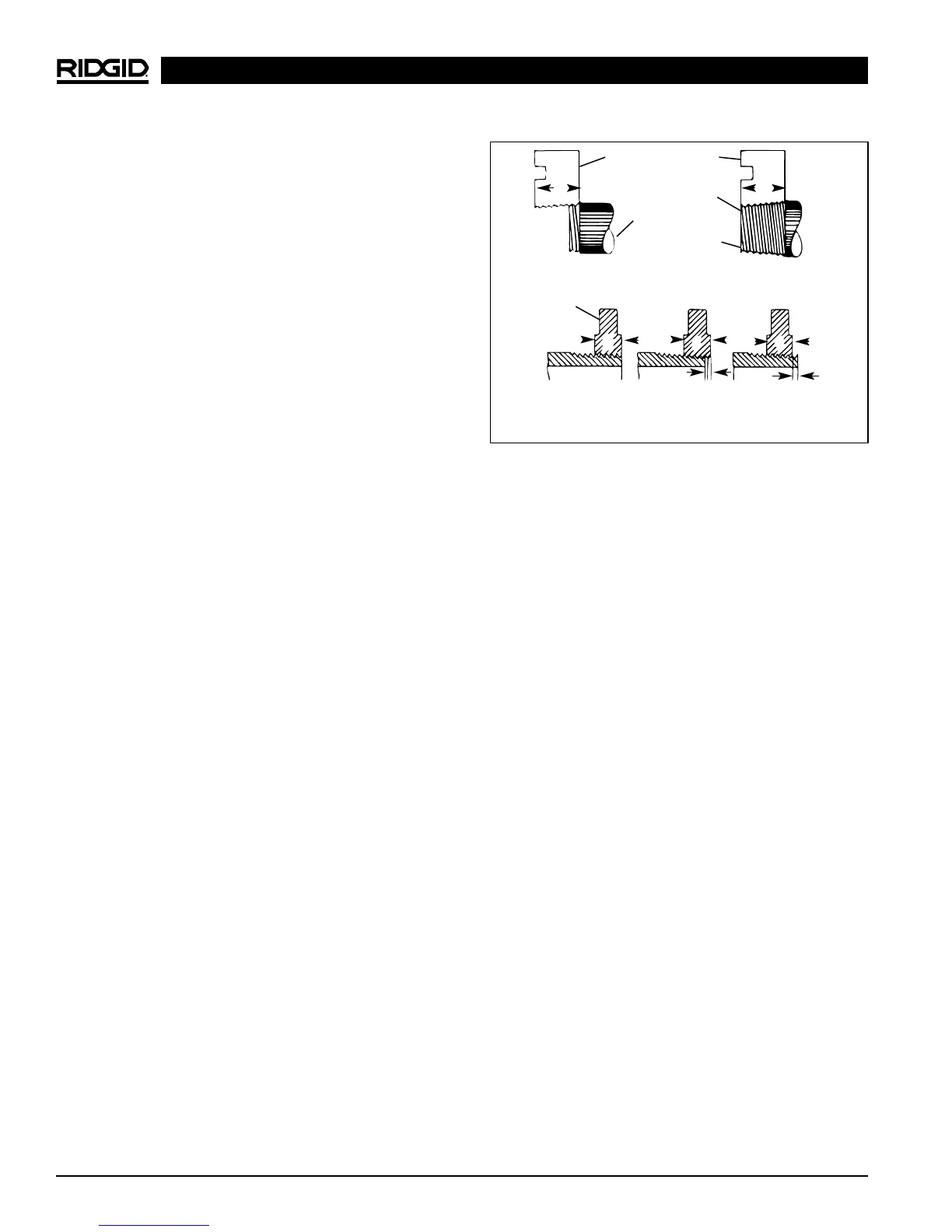
Figure 18 – Checking Thread Length
NOTE! If a ring gage is not available, a fitting can be
used. This fitting should be representative of those
being used on the job. The pipe thread should be
cut to obtain 2 or 3 turns hand tight engagement
with fitting. If pipe thread is not proper diameter the
index line should be moved in the OVER or
UNDER size mark on size bar. (refer to “Installing
Dies In Die Heads”).
NOTE! Receding dies used in 714/914 Head are NOT
full width dies!
No. 766 Saran Cutter
Installing No. 766 Saran Cutter
1. Latch Carriage Sine Bar Hook (OUT) over edge of car-
riage so cutter does not hit Sine Bar. (Figure 19)
2. Replace No. 764 Wheel-Type Cutter with No. 766
Blade Type Cutter.
3. Position Tool Bit such that cutting edge extends
1
/
32
″
below tool holder slide. Tighten securely.
1224 Threading Machine
Ridge Tool Company14
7. Reinstall die head washer and tighten size adjusting
nut.
Installing Dies In No. 713 and 913
Quick-Opening Die Heads (L.H. Only)
The Nos. 713 and 913 Die Heads (Figure 10) for left-
hand threads require three sets of dies to thread pipe
ranging from
1
/
4
″ through 2″. One set of dies is required
for each of the following pipe size ranges: (
1
/
4
″ -
3
/
8
″), (
1
/
2
″ -
3
/
4
″) and (1″ - 2″).
1. Lay die head on bench with numbers face up.
2. Move throwout lever to OPEN position.
3. Loosen clamp lever approximately three turns.
4. Lift tongue of clamp lever washer up out of slot under
size bar. Slide throwout lever all the way to end of slot
in the OVER direction indicated on size bar.
5. Remove worn dies from die head.
6. Insert new dies to mark. Die numbers 1 through 4
must agree with those on die head.
7. Slide throwout lever back so that tongue of clamp
lever washer will drop in slot under size bar.
8. Adjust die head size bar until index line on lock screw
or link is aligned with proper size mark on size bar.
(For bolt threads, align Index line with BOLT line of
size bar.)
9. Tighten clamp lever.
10. If oversize or undersize threads are required, set the
index line in direction of OVER or UNDER size mark
on size bar.
Checking Thread Length
1. Thread is cut to proper length when end of pipe is
flush with edge of dies (Figure 18A).
2. Die head is adjustable to obtain proper thread diam-
eter. If possible, threads should be checked with a
thread ring gage (Figure 18B). A proper thread is cut
when end of pipe is plus or minus one turn of being
flush with face of ring gage.
WW
D
D
D
Die
Pipe
Die
Pipe
A - Full Width Die Thread
Starting to Cut Thread
Flush
(Basic Size)
One Turn Large
(Maximum Size)
One Turn Small
(Minimum Size)
Thin Ring
Gage
Completed Thread
Die Flush
With End
of Pipe
B - Checking Threads Within Pipe Gage


 To Next Page