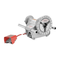
1224 Threading Machine
Ridge Tool Company16
4. Cock die head.
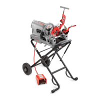
5. Move carriage handwheel towards pipe until leading
edge of die is flush with pipe. (Figure 21)
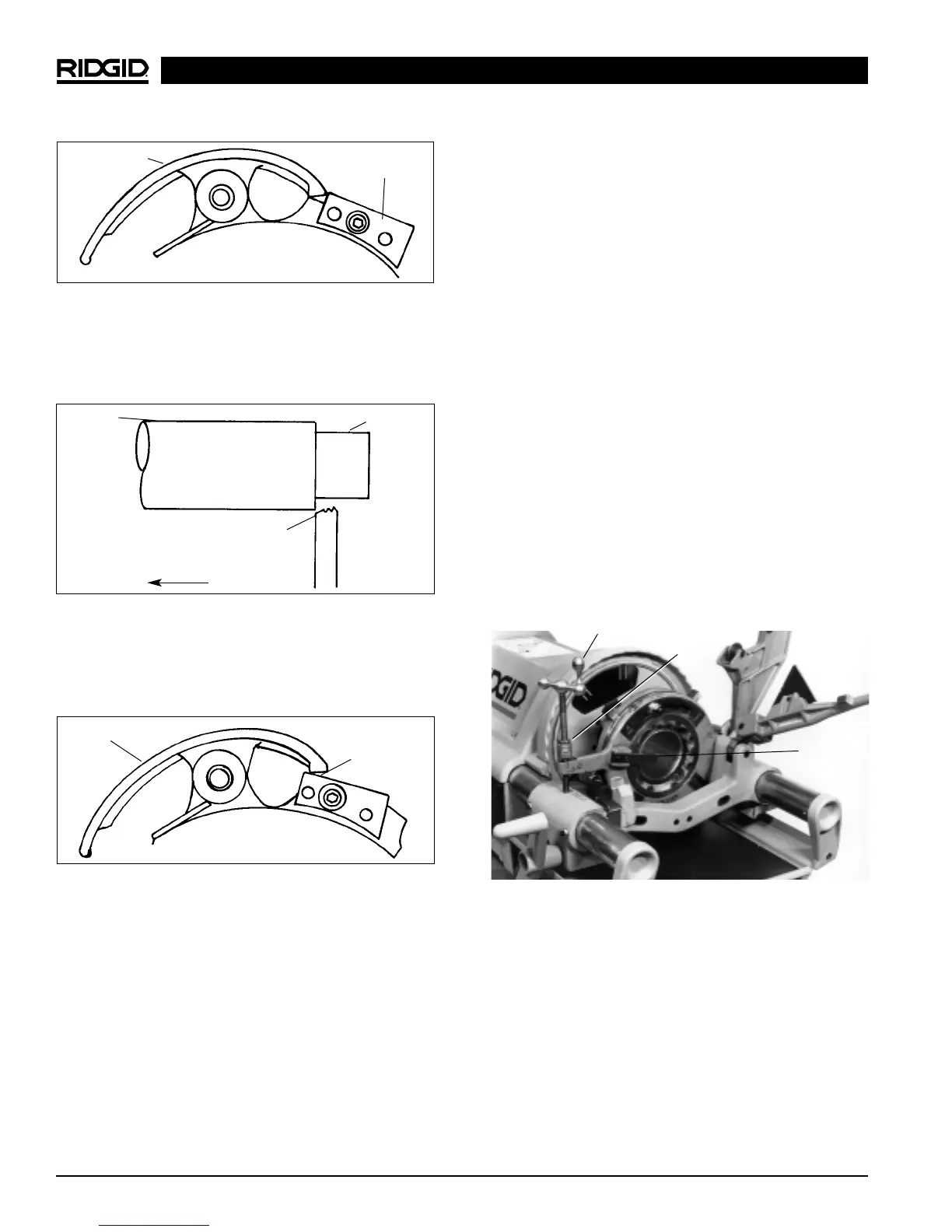
6. Push release lever so that it rests on top of lockout
plate and begin a normal thread with carriage hand-
wheel. (Figure 22)
No. 725 Cut Groove Die Head
Grooving Pipe with No. 725 Cut Grooving
Die Head
(Figure 23)
1. Install proper die set. Refer to Die Installation proce-
dure.
2. Latch carriage sine bar hook (OUT) over edge of
carriage so die head does not hit sine bar.
3. Swing cutter and reamer to UP position.
4. Adjust die head to proper size.
5. Fully loosen feed screw assembly so that dies do
not contact O.D. of pipe.
6. With pipe securely tightened in front chuck, turn car-
riage handwheel counter-clockwise to bring die head
stop against end of pipe.
7. Set speed of machine at 36 RPM.
8. Turn REV/OFF/FOR switch to FOR position and step
on foot switch.
9. Slowly turn feed screw assembly to feed grooving
bits into pipe to start cut groove.
10. Before locking stop nuts to set grooving dies to proper
depth of cut, allow pipe to make 3 to 4 revolutions to
clean up any extra material left in groove.
11. Lock stop nuts against roll housing.
12. Turn feed screw assembly counter-clockwise to back
off grooving dies from pipe.
NOTE! Leaving stop nuts locked in position will assure
further cuts are the same depth.
13. Once cutting operation is complete and while pipe is
still rotating, retract cutting tool.
Figure 21 – Position Leading Edge of Chaser Flush with
Pipe
Figure 22 – Positions of Release Lever and Lockout
Plate to Begin Standard Length Thread
Pipe
Liner
Carriage Travel
Leading Edge of Die
Release Lever
Position to
Begin a
Standard
Length Thread
Figure 23 – No.725 Cut-Groove Die Head
Feed Screw
Pipe Stop
Stop
Nuts
Release Lever
Lockout Plate
Figure 20 – Adjust to Position Above with Die Head
Cocked.


 To Next Page