RIGOL
© 2008 RIGOL Technologies, Inc.
User‟s Guide for Logic Signal Output Module
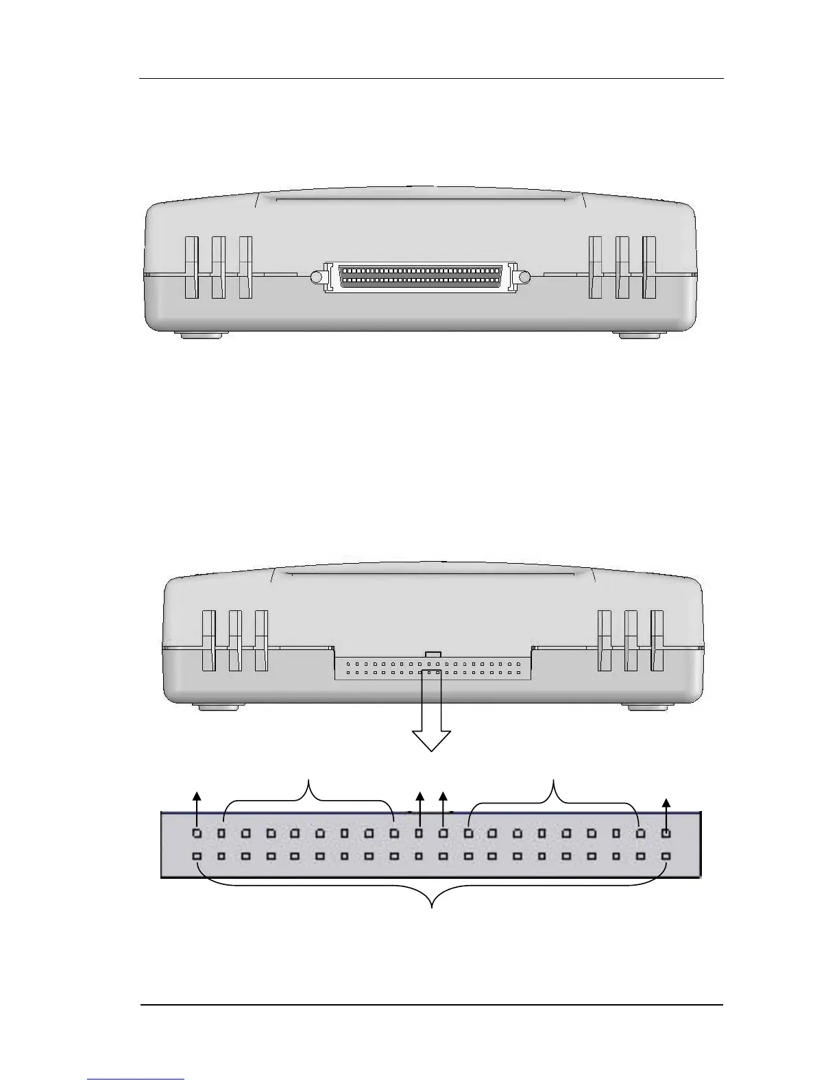
As shown in Figure 1-2, to use the module, please connect this port to the
“DIGITAL OUTPUT” connector at the rear panel of DG3000 with the provided cable
as described in “Appendix A”.
Figure 1-2 Port used for connecting to DG3000
The analog logic output port and the pin definitions are shown in Figure 1-3. To
use it, please connect the provided logic analyzer testing wires to this port;
connecte the other ends of the testing wires to the input of a logic analyzer which
will verify the output signal of the module. The logic analyzer testing wires can also
be used to transform the analog logic output.
Figure 1-3 Port instruction of the analog logic output
 Loading...