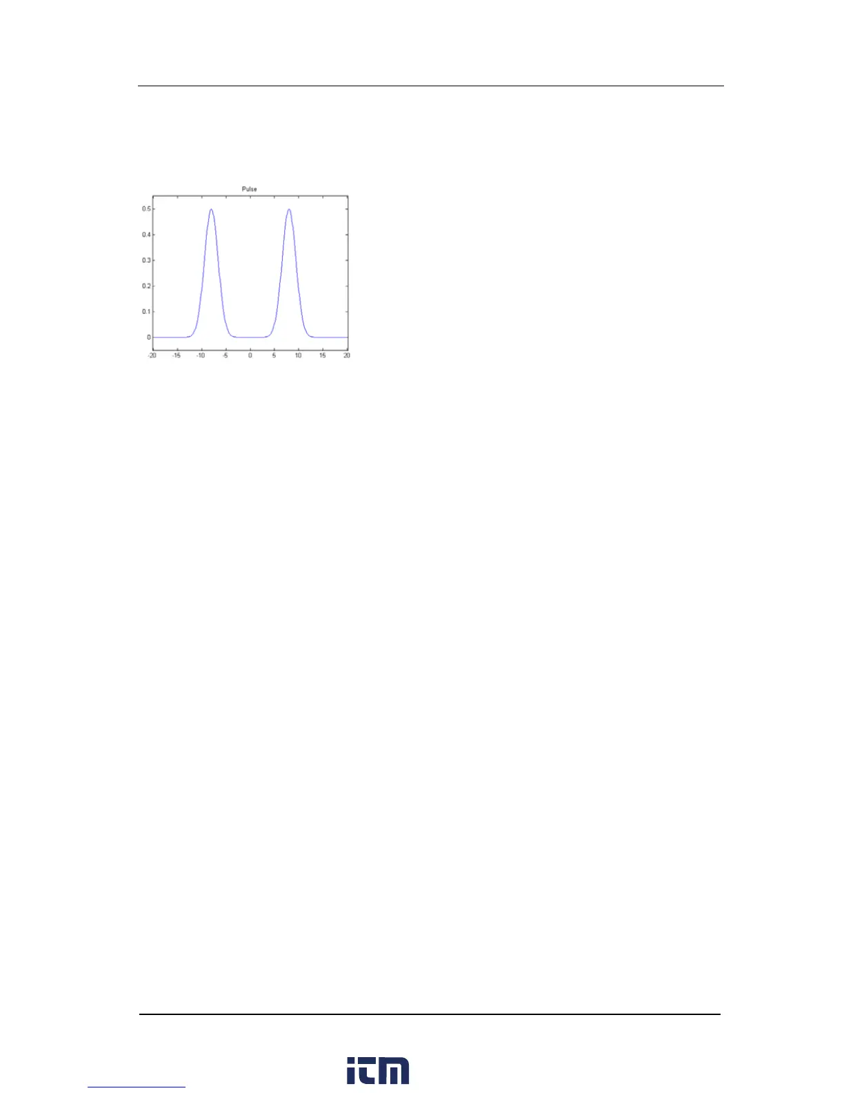
Pulse
The figure below shows a simulated Pulse waveform.
The Pulse mentioned here can be configured by setting the parameters “Pulse
Width/Duty Cycle”, “Leading” and “Trailing”.
Pulse Width/Duty Cycle: The minimum Pulse Width is related to the current edge
time, ranging from 4 ns to “Pulse Period - 12 ns”, while Duty Cycle ranges from
0% to 100%.
Leading: ranges from 2.5 ns to 1.9531 ks, and relates to the pulse period, pulse
width and the trailing edge.
Trailing: ranges from 2.5 ns to 1.9531 ks, and relates to the pulse period, pulse
width and the leading edge.
w ww. . com
information@itm.com1.800.561.8187