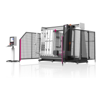
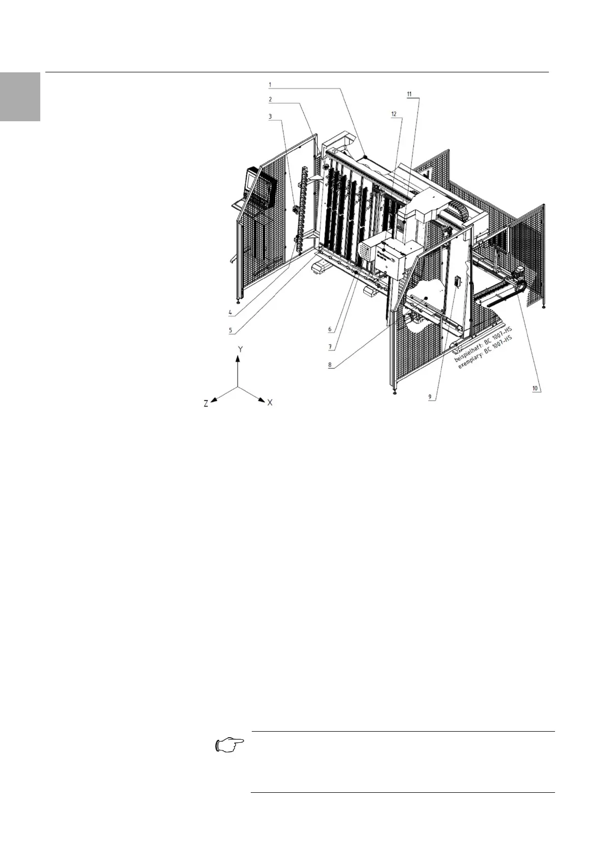
Fig. 4: Perforex BC components with BC 1007 HS as example
Legend
1 Enclosure
2 Tool breakage check
3 Pneumatic clamping device operation
4 Tool magazine
5 Panel machining
6 Pneumatic clamping device
7 Spindle
8 Cube machining
9 Cube clamping operation
10 Motorised depth adjustment
11 Gantry
12 Cross-slide
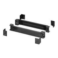
The clamping serves to store and secure the workpieces to be machined.
Limit stops to position the workpiece are located on the left-hand operating
side as well as in the lower area. After placing the part, the mechanical
clamping brackets (Fig. 8) are applied and clamped.
The spacer bolts are placed in the envisaged drill holes of the machine table
as appropriate for the part size.
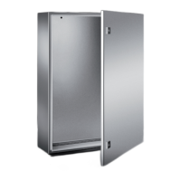
3.1.3 Enclosure
The enclosure contains all controllers and drives required for operation. The
machine main switch is located here. The enclosure is ventilated / climate-
controlled (optional). This ensures maximum performance of the machine.
Note:
Check the filter elements of the enclosure ventilation / climate
control regularly in order to extend the service life of the drive
components and to ensure maximum performance of the drives.