Rockwell Automation Publication 1715-UM001J-EN-P - December 2020 135
Chapter 5
Using 1715 Analog I/O Module Features
1715 Analog Module
Overview
The 1715 analog I/O modules mount in a 1715 Redundant I/O System and use an
I/O termination assembly that is mounted in an I/O base unit to communicate
via redundant 1715 adapters.
Before you install and use your module, you must do the following:
• Install and ground a user-supplied, 24V DC power supply.
• Determine whether you are using your analog I/O module in Simplex or
Duplex mode.
• Install the correct termination assembly that is based on your
determination for either simplex or duplex operation.
Each analog I/O module is an isolated module that plugs into one position of
the I/O base unit and a termination assembly that is mounted to the base unit.
Analog I/O modules can be configured in Logix Designer programming
software as simplex (not redundant) or duplex (redundant).
Termination assemblies provide termination for the field I/O channels and, by
the use of coding pegs and sockets, are matched to a specific analog I/O
module. Module keying can also be set in the RSLogix 5000® or Logix Designer
project. Field connections are made at the terminal block connectors on the
termination assembly.
The analog I/O modules and termination assemblies for the 1715 Redundant
I/O System are as follows.
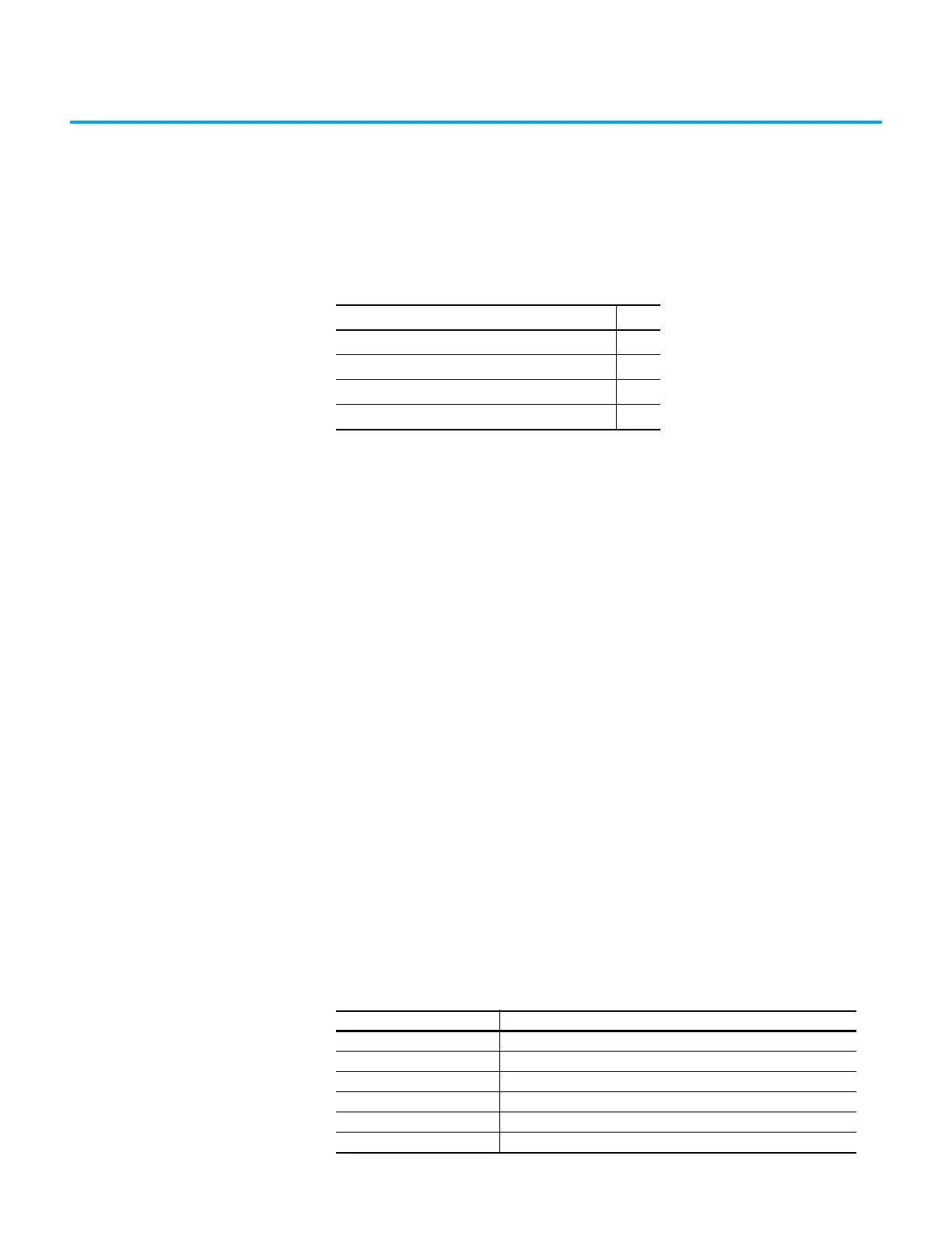
Topic Page
1715 Analog Module Overview 135
Features Common to All Analog I/O Modules 137
Scaling 139
Operating Modes 139
Table 18 - Types of ControlLogix® Analog I/O Modules and Components
Cat. No. Description
1715-IF16 16-channel analog input module
1715-OF8I 8-channel analog output module
1715-TASIF16 16-channel analog input simplex termination assembly
1715-TADIF16 16-channel analog input duplex termination assembly
1715-TASOF8I 8-channel analog output simplex termination assembly
1715-TADOF8I 8-channel analog output duplex termination assembly

 Loading...


