EasyManuals Logo

Rockwell Automation Allen-Bradley 1715-AENTR User Manual

Rockwell Automation Allen-Bradley 1715-AENTR
298 pages
To Next Page IconTo Next Page
To Previous Page IconTo Previous Page
Page #99 background imageLoading...
Page #99 background image
Rockwell Automation Publication 1715-UM001J-EN-P - December 2020 99
Chapter 2 Installation Instructions
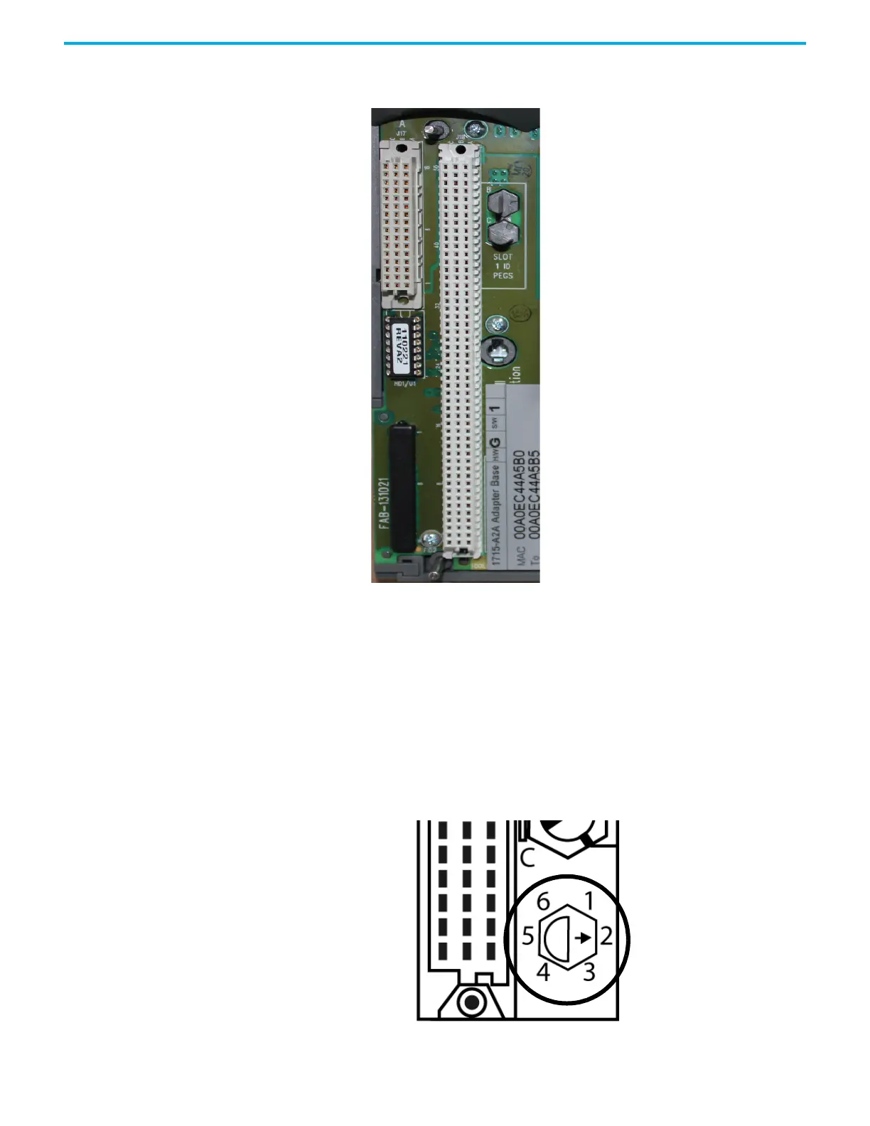
Figure 59 - Inserted Coding Pegs for Adapter Base Unit
Verify Coding Pegs
To verify that each coding peg, also known as a polarizing pin, is positioned
correctly, follow these steps.
1. Review the diagram on the adapter base unit that shows the six possible
positions for a coding peg.
32062 M

Table of Contents

Questions and Answers:

Question and Answer IconNeed help?

Do you have a question about the Rockwell Automation Allen-Bradley 1715-AENTR and is the answer not in the manual?

Rockwell Automation Allen-Bradley 1715-AENTR Specifications

General IconGeneral
BrandRockwell Automation
ModelAllen-Bradley 1715-AENTR
CategoryI/O Systems
LanguageEnglish

Related product manuals