98 Rockwell Automation Publication 1715-UM001J-EN-P - December 2020
Chapter 2 Installation Instructions
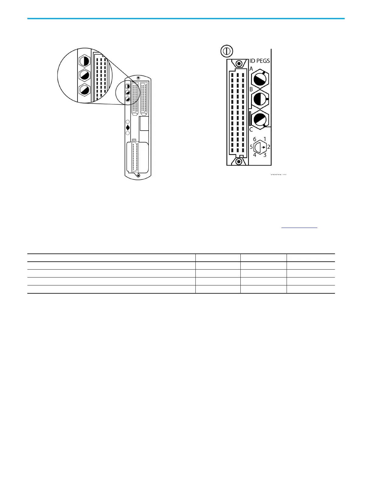
Figure 58 - Module Coding Peg Sockets and Positions
The legend for the coding pegs showing the peg positions is shown on the
lower left of the adapter base unit and on each I/O termination assembly. The
positions are numbered 1…6. The three coding pegs are lettered A, B, and C
with A being on the top. Each peg, or key, is fitted in the base unit so that the
index recess is next to the relevant numbered position. See
Figure 59, which
shows a photograph of the Adapter Base Unit. Coding peg A is absent.
Coding Peg Positions
32062 M
32085 M
Coding Peg Socket
Table 12 - Allocations of Coding Pegs
Application Key A Key B Key C
1715 Adapter Base Unit Not Available 2 1
1715 Digital Input Termination Assemblies 2 1 1
1715 Analog Input Termination Assemblies (for analog input modules) 2 1 3
1715 Digital Output Termination Assemblies (for digital output modules) 3 1 1

 Loading...


