94 Rockwell Automation Publication 1715-UM001J-EN-P - December 2020
Chapter 2 Installation Instructions
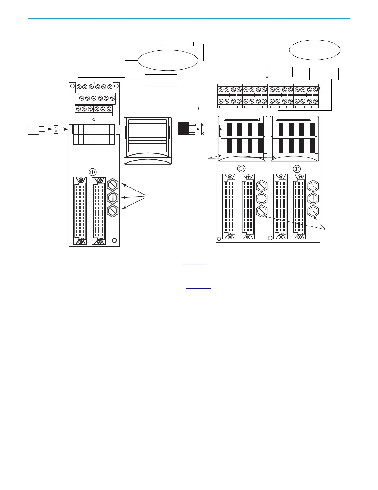
Figure 54 - Connection of 120 Ω Assemblies and Secondary Masters to Terminal Blocks
The left circuit of Figure 54 above represents the secondary master connected
to the Channel 2 terminal of a simplex termination assembly.
The right circuit of Figure 54
above represents the secondary master connected
to the Channel 9 terminals of a duplex termination assembly.
For both circuits the secondary master is powered through a field power
supply unit.
Recommended Wiring for Analog Output Modules
This section describes the wiring for analog outputs.
32120 M
Fuse
Fuse
Holder
Channel -
Channel +
TB1 TB2
CH0 CH1 CH2
CH3
CH4CH5 CH6 CH7 CH8CH9
CH10CH11CH12
CH13
CH14
CH15
FS1 FS3 FS5 FS7
FS2
J1
16
cc cc
11 11
16 16 16
J2 J4
J3
FS4 FS6 FS8
FS9 FS11 FS13 FS15
FS10 FS12 FS14 FS16
120 Ω
HART
Secondary Master
Field Connections This Side
FH1
FH2
FH7
FH6
FH5
FH4
FH3
FH9
FH8
FH10
FH16
FH15
FH14
FH13
FH12
FH11
FH1
F1
OV OV CH0
CH1 CH2 CH3
CH4 CH5 CH6 CH7 CH8 CH9
CH10 CH11 CH12 CH13 CH14 CH15
TB1
TB2
J1
J2
16
16
11
1715-TADIF16
Analog Input Duplex
Termination Assembly
1715-TASIF16
Analog Input Simplex
Termination Assembly
45238
32120 M
Terminal Block Cable This Side
Fuse Cover
Fuse Covers
Coding Peg
Coding
Pegs
HART
Secondary Master
120 Ω
0 V

 Loading...


