Rockwell Automation Publication 1715-UM001J-EN-P - December 2020 267
Appendix B 1715-IB16D Digital Input Module Diagnostics
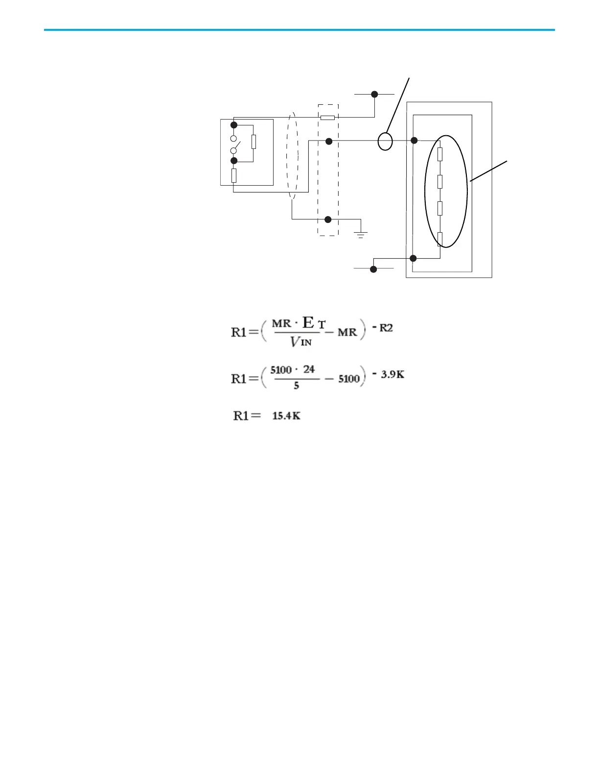
In this example, 15.4 kis a close standard value, so we use 15 k, which
changes the voltage slightly, but not enough to make us change our range.
Calibration Drift Checks The 1715I/O analog modules are calibrated at the factory with a default
calibration. As time passes, the electrical specifications of various electronic
components of your analog module drift.
To make sure the best possible accuracy in measurements that your analog
input module makes and signals that your analog output module generates are
maintained, it is recommended to perform a calibration drift check every two
years for most applications.
Although the purpose of checking the calibration of analog modules is the
same for input and output modules, to verify that the accuracy and
repeatability of the module is maintained, the procedures that are involved
differ per module.
When you check the calibration of input modules, you use current, voltage, or
ohms calibrators to send a signal to the module and check the correct values
are reported.
Shield
(if used)
Terminal
Blocks
OV
20Ω
100Ω
50 mA
4.99kΩ
Termination
Assembly
+24V DC
R1
R2
45678
5V DC
5.1 k
SW1
3.9 k

 Loading...


