Rockwell Automation Publication 1715-UM001J-EN-P - December 2020 49
Chapter 2 Installation Instructions
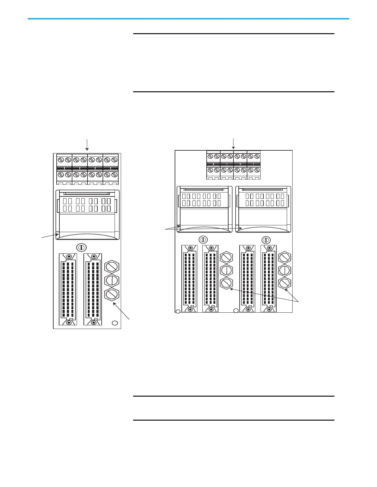
Figure 22 - 1715-TASOF8 and 1715-TAD0F8 Analog Output Termination Assemblies
1715-C2 Expansion Cable
A 2 m (6.56 ft) expansion cable is available to connect I/O modules to field
devices, and to allow for space restrictions within the enclosure of the system.
IMPORTANT
The dual termination assembly does this by supporting inter-
module communication for current sync operation and by routing
the channel outputs from two 8-channel analog output modules
in parallel to 8 field devices. Therefore, each field device
receives a current source from a channel on each of two
modules. So if one module fails, or one or more channels fail on a
module, the outputs from the second module continues to supply
the field devices.
J1 J2
cc
CH0 1 2 3 4 5 6 7
CH
LOOP-
DAOTA
PCB130861 REV A
LOOP+
TB1
J1 J2 J4
J3
01
TB2
23
TB3
45
TB4
67
1715-TASOF8
Analog Output Simplex
Termination Assembly
1715-TADOF8
Analog Output Duplex
Termination Assembly
32122 M
32123 M
IMPORTANT
• 1715-C2 cables must be secured when installed; use the provided
screws to secure the cable.
• 1715-C2 cables are rated 30V/9.6 A.

 Loading...


