Rockwell Automation Publication 1715-UM001J-EN-P - December 2020 57
Chapter 2 Installation Instructions
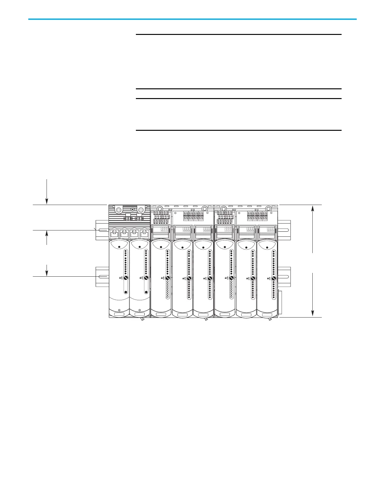
DIN rail mounting is shown in the following figure.
DIN Rail Assembly The 1715 Redundant I/O System is mounted on DIN rails within an enclosure.
Pay special attention to dimensions needed for base unit placement.
For each pair of DIN rails, mount the lower rail with its center line
101 mm (3.98 in.) below the center line of the upper rail.
Free space must also be provided on each end of the DIN rail for the end stops,
if necessary.
IMPORTANT
Allow sufficient free space around the base units. Every
installation needs space on at least three sides, as follows:
• Space above, to manipulate and install field wiring
• Space below, to enable modules to fit and to be able to grasp a
module during removal
• Space to the right, to maneuver an I/O base unit during assembly
or in the event of installing a new base unit
IMPORTANT
Minimum clearance between the product and the adjacent
equipment must be 15.3…20 cm (6.0…8.0 in.) between chassis
and a heat source, and allow 5.1 cm (2.0 in.) between wireway and
top or bottom of chassis.
IO BASE
1715-A310
CH1
CH1
CH1
CH1
CH1
CH1
CH1
CH1
TERMINAL IDENTITY
AOTA
Dual.
CH1
CH1
CH1
CH1
CH1
CH1
CH1
CH1
TERMINAL IDENTITY
AOTA
Dual.
CH1
CH1
CH1
CH1
CH1
CH1
CH1
CH1
TERMINAL IDENTITY
AOTA
Dual.
Module Status
Redundancy Status
Network Status
Rack Status
Ethernet 1
Ethernet 2
Reset
Ethernet 1
Ethernet 2
Reset
Channel 00
Channel 01
Channel 02
Channel 03
Channel 04
Channel 05
Channel 06
Channel 07
Channel 08
Channel 09
Channel 10
Channel 11
Channel 12
Channel 13
Channel 14
Channel 15
IO BASE
1715-A310
CH1
CH1
CH1
CH1
CH1
CH1
CH1
CH1
TERMINAL IDENTITY
AOTA
Dual.
CH1
CH1
CH1
CH1
CH1
CH1
CH1
CH1
TERMINAL IDENTITY
AOTA
Dual.
CH1
CH1
CH1
CH1
CH1
CH1
CH1
CH1
TERMINAL IDENTITY
AOTA
Dual.
Healthy
Ready
Run
Module Status
Redundancy Status
Network Status
Rack Status
Healthy
Ready
Run
Healthy
Ready
Run
Healthy
Ready
Run
Healthy
Ready
Run
Healthy
Ready
Run
Channel 00
Channel 01
Channel 02
Channel 03
Channel 04
Channel 05
Channel 06
Channel 07
Channel 08
Channel 09
Channel 10
Channel 11
Channel 12
Channel 13
Channel 14
Channel 15
Channel 00
Channel 01
Channel 02
Channel 03
Channel 04
Channel 05
Channel 06
Channel 07
Channel 00
Channel 01
Channel 02
Channel 03
Channel 04
Channel 05
Channel 06
Channel 07
Channel 08
Channel 09
Channel 10
Channel 11
Channel 12
Channel 13
Channel 14
Channel 15
Channel 00
Channel 01
Channel 02
Channel 03
Channel 04
Channel 05
Channel 06
Channel 07
Channel 08
Channel 09
Channel 10
Channel 11
Channel 12
Channel 13
Channel 14
Channel 15
Channel 00
Channel 01
Channel 02
Channel 03
Channel 04
Channel 05
Channel 06
Channel 07
32058 M
46 mm
(1.81 in.)
101 mm
(3.98 in.)
Each Base Unit (Two Shown) Occupies
126 mm (4.96 in.) Width
233 mm
(9.17 in.)

 Loading...


