Rockwell Automation Publication 1715-UM001J-EN-P - December 2020 73
Chapter 2 Installation Instructions
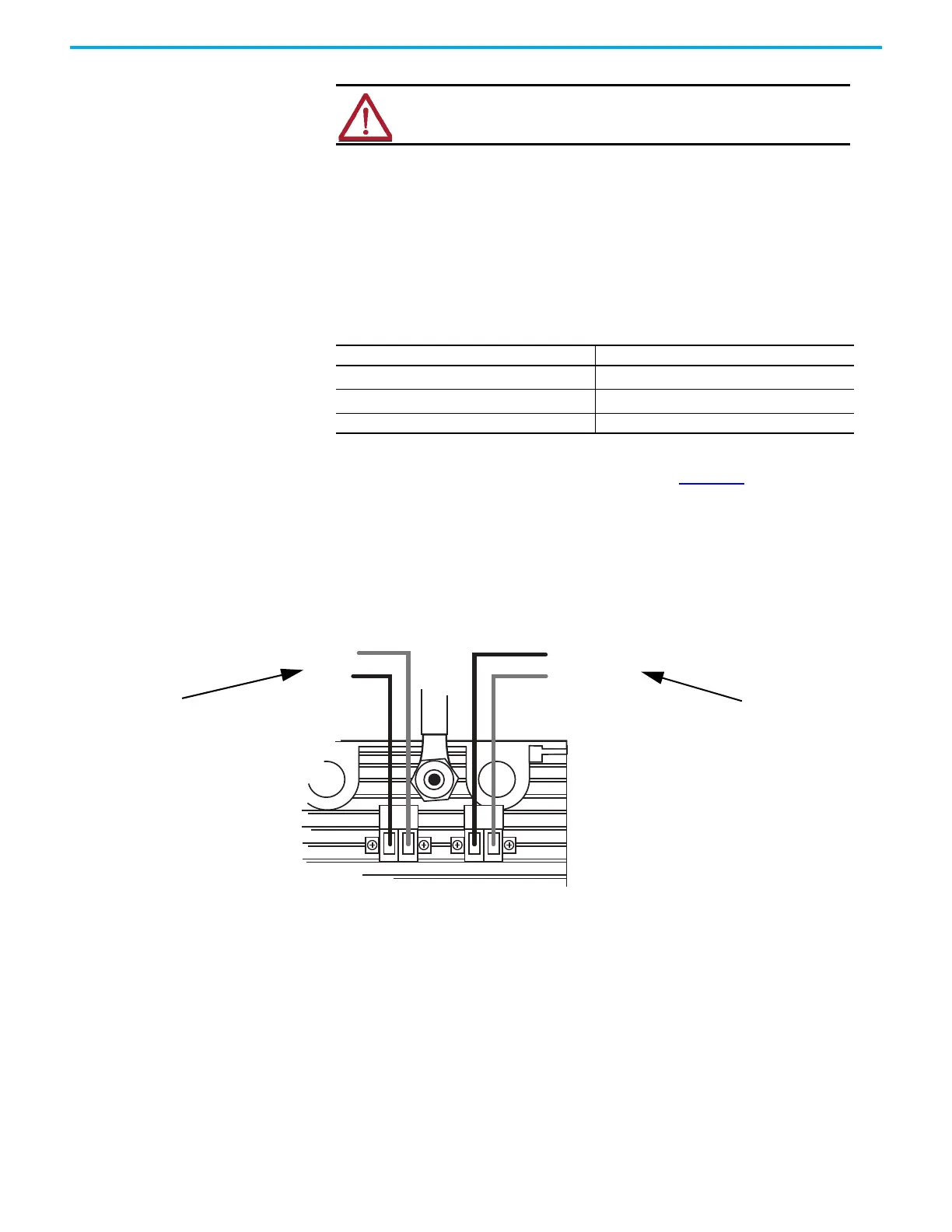
For each power supply connection, follow these steps.
1. Connect the negative line from the power supply, typically labeled ‘OV’, to
the left-hand terminal.
2. Connect the positive line from the power supply, typically labeled ‘+24V’,
to the right-hand terminal.
3. Apply a minimum tightening torque of 0.5 N•m (0.37 lb•ft) to the
terminal screws.
For maximum protection, be sure that the PWR-1 and PWR-2 plugs are
supplied from independent 24V DC sources as in Figure 29
. Only having one
power supply plug connection causes a Rack Status fault status indicator to
illuminate on adapters.
Figure 29 - Independent Power Sources
Wire the Ground Connection
The system can have up to three separate ground systems:
• An AC Safety Ground (sometimes called the ‘dirty ground’) to help
protect you in the event of a fault. The ground stud on the adapter base
unit must be connected to the AC safety ground, along with all exposed
metalwork, such as DIN rails.
• An Instrument Ground (sometimes called the ‘clean ground’ or ‘OV DC
ground’) to provide a good stable OV reverence for the system. Every
signal return must be referenced to the instrument ground, which is
isolated from the AC Safety Ground.
ATTENTION: To comply with UL restrictions, all connections to this
equipment must be powered from a UL Listed source compliant with
Limited Voltage/Current per UL 508.
Table 10 - - Module Power Wiring Sizes
Wiring Attribute Size
Conductor cross section, stranded maximum
2.5 mm
2
(12 AWG)
Conductor cross section, solid maximum
2.5 mm
2
(12 AWG)
Stripping length 7 mm (9/32 in.)
MP-PWR-24V1
OV
MP-PWR-24V2
OV

 Loading...


