80 Rockwell Automation Publication 1715-UM001J-EN-P - December 2020
Chapter 2 Installation Instructions
Apply a minimum tightening torque of 0.5 N•m (0.37 lb•ft) to the terminal
screws.
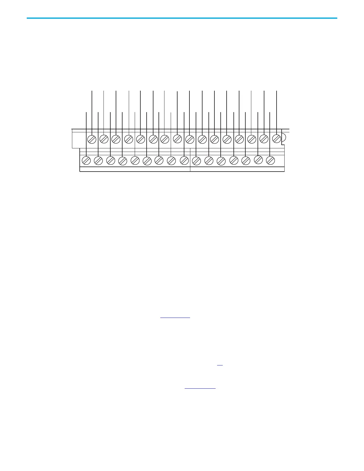
Figure 37 - Connections to 1715-TADIB16D Duplex Digital Input 16-channel Termination Assembly
Apply a minimum tightening torque of 0.5 N•m (0.37 lb•ft) to the terminal
screws.
Digital Input Slew Tolerance
It is possible during sustained periods of abnormal input voltage slewing that
channels can be declared faulted as a consequence of diagnostics that are
otherwise designed to verify the channels are operating within their designed
safety accuracy.
To avoid spurious declaration of channel faults, it is necessary to ensure that
the input signal condition satisfies the maximum slew rate criteria that are
defined in the 1715 Redundant I/O System Specifications Technical Data,
publication 1715-TD001. So it can be necessary to condition the input signal
with low-pass filtering.
Field Loop Circuits for Digital Inputs
The recommended digital input field loop circuits for the 1715-IB16D digital
input module are shown on page 75
.
For line monitored digital input loop circuit wiring and recommended
threshold values, see Appendix B
.
Recommended Circuits for Digital Outputs
This circuit is suitable for simplex and duplex configurations of digital output
modules. The two 10 A fuses that are shown are supplied with the adapter in
TB2
TB1
CH0 - CH1 - CH2- CH3- CH4- CH5- CH6- CH7- CH8- CH9-CH10-CH11-CH12-CH13-CH14- CH15-
CH0+CH1+CH2+ CH3+CH4+CH5+CH6+CH7+ CH8+CH9+CH10+CH11+CH12+CH13+CH14+CH15+

 Loading...


