68 Rockwell Automation Publication 1715-UM001J-EN-P - December 2020
Chapter 2 Installation Instructions
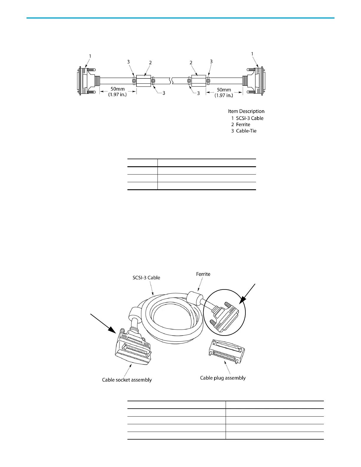
Fit the ferrites 50 mm (1.97 in.) from each end and secure with cable ties either
side of the ferrites.
Table 8 - Cable Assembly
Expansion Cable
The expansion cable has a left cable adapter and a right cable adapter. Connect
one end to the right-hand bus connector of an I/O base (or adapter base) unit.
The other end connects to the left-hand bus connector of an I/O base unit.
Figure 27 - I/O Expansion Cable Adapters
Item Description
1SCSI-3 cable
2 Ferrite
3 Cable-tie
Cable Adapter
32086 M
Cable Adapter
Item Description
1 Cable socket assembly
2SCS1-3 cable
3 Ferrite
4 Cable plug assembly

 Loading...


