254 Rockwell Automation Publication 1715-UM001J-EN-P - December 2020
Appendix A Status Indicators
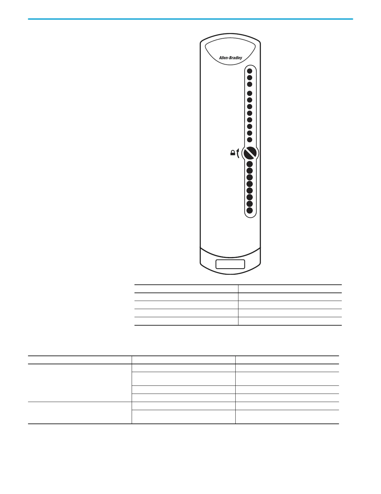
Status indicators for the 1715-IF16 analog input module are shown in this table.
Indicator Description
A Healthy - general status display
B Ready- redundancy status indicator
C Run- network status indicator
D Channel 0…7, 8…15 - channel status indicators
Channel 00
Channel 01
Channel 02
Channel 03
Channel 04
Channel 05
Channel 06
Channel 07
1715-IF16
ANALOG INPUT
Channel 08
Channel 09
Channel 10
Channel 11
Channel 12
Channel 13
Channel 14
Channel 15
Healthy
Ready
Run
Table 57 - Analog Input Module Status Indicators
Indicator State Description
Healthy
Steady off No power.
Steady green
Module operational - The module has been
configured and is operating without any faults.
Flashing green Standby - The module has not been configured.
Steady red Fault - A fault has been detected on the module.
Ready
Steady off No power or no partner module present.
Steady green
Synchronized - Synchronized with partner module;
redundant operation.

 Loading...


