256 Rockwell Automation Publication 1715-UM001J-EN-P - December 2020
Appendix A Status Indicators
Status indicators for the 1715-OF8I analog output module are shown in this
table.
B Ready - redundancy status indicator
C Run - network status indicator
D Channel 0…7 - channel status indicators
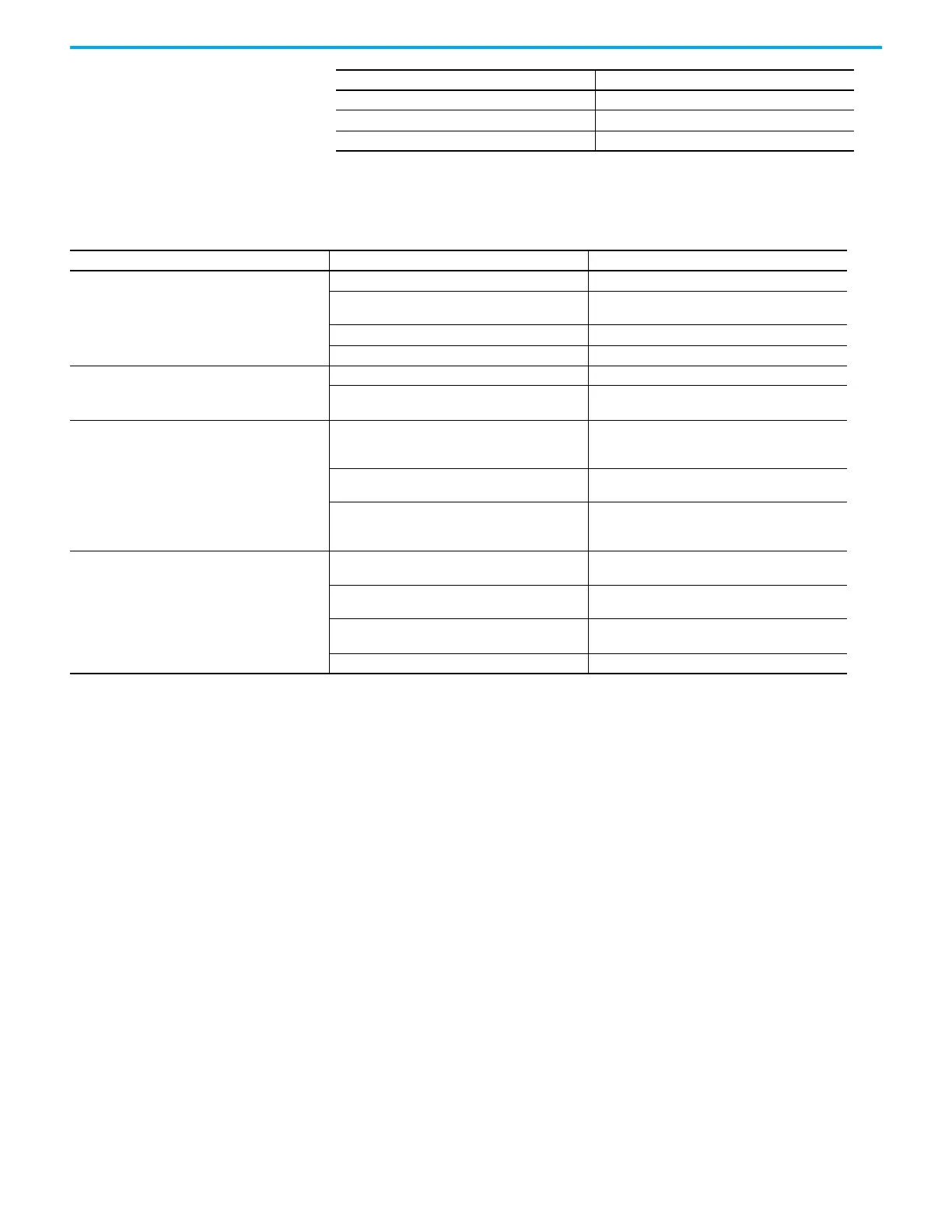
Indicator Description
Table 58 - Analog Output Module Status Indicators
Indicator State Description
Healthy
Steady off No power.
Steady green
Module operational - The module has been
configured and is operating without any faults.
Flashing green Standby - The module has not been configured.
Steady red Fault - A fault has been detected on the module.
Ready
Steady off No power or no partner module present.
Steady green
Synchronized - Synchronized with partner module;
redundant operation.
Run
Steady off
No power; no backplane communication - No power
or the module is not communicating over the
backplane.
Steady green
Connected - The module has at least one established
connection.
Flashing green
No connections - The module is communicating over
the backplane, but there are no established
connections.
Channel 0…7
Steady off
Off/de-energized - The channel is not being driven
(that is, output current < 0.4 mA).
Steady amber
On/energized - The channel is being driven (i.e.
output current is >= 0.4 mA).
Flashing amber
Field fault - A field fault has been detected on this
channel.
Steady red Fault - A fault has been detected on this channel.

 Loading...


