40 Rockwell Automation Publication 2198-RM004C-EN-P - March 2022
Chapter 3 Connectors
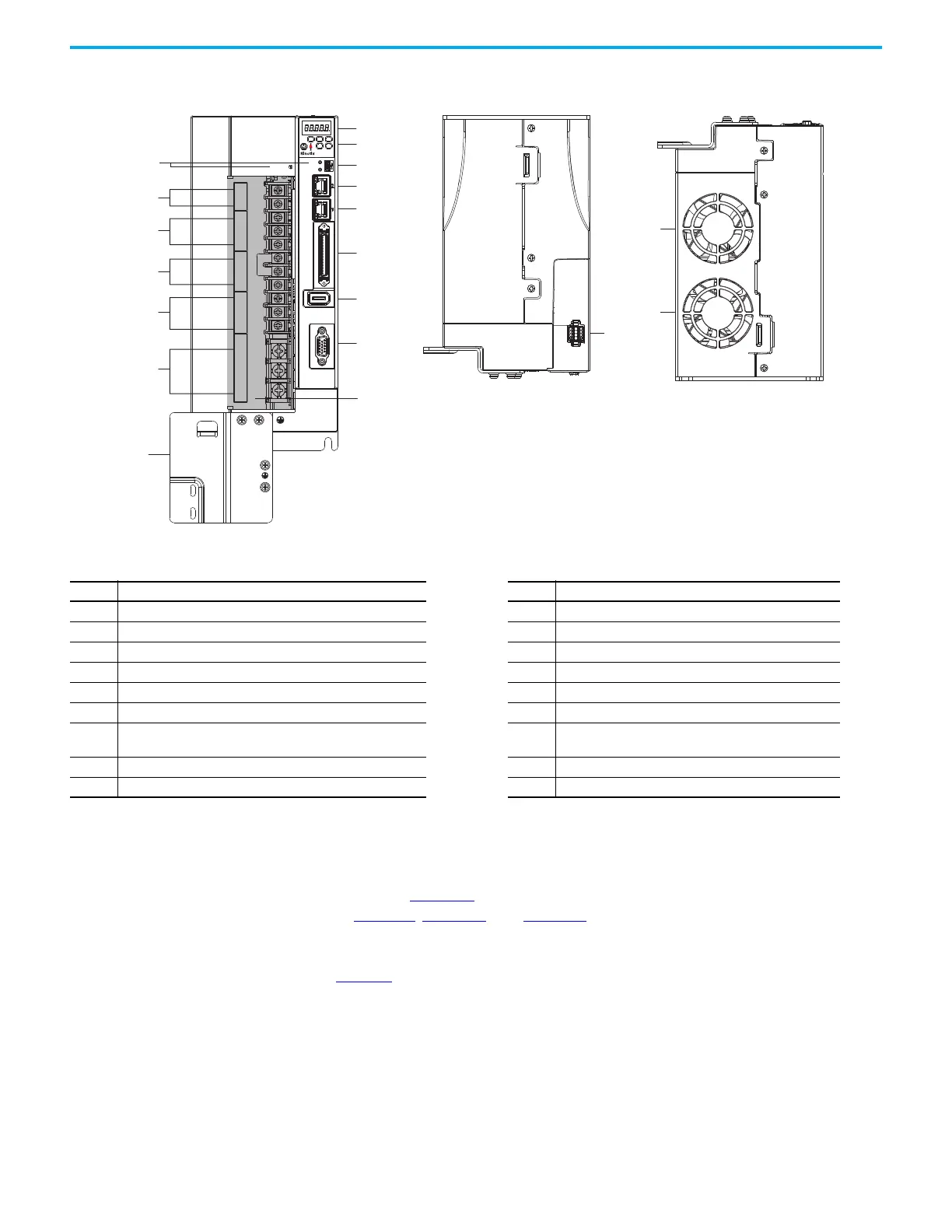
Figure 14 - Features and Indicators (catalog numbers 2198-E2055-ERS, 2198-E2075-ERS, 2198-
E2150-ERS, 2198-E4055-ERS, 2198-E4075-ERS, and 2198-E4150-ERS)
I/O Connector Pinouts This section describes the I/O Connector pin assignments and compares the
pin assignments for the Kinetix 300 Servo Drive and the Kinetix 5100 Servo
Drive. See Figure 10
for locations of connectors on your Kinetix 300 drive. See
in Figure 11
, Figure 12, and Figure 14 for locations of connectors on your
Kinetix 5100 drive.
Table 45
compares the I/O connector pin assignments for the Kinetix 300 (IOD
connector) and Kinetix 5100 servo drives (I/O connector).
14
9
16
3
12
11
2
13
8
15
7
6
5
4
1
10
17
17
18
P1
P2
DC–
L1
L2
L3
L1C
L2C
DC+
ESH
U
V
W
NET
MOD
CHARGE
5100
I/O
AUX
STO
MFB
Table 44 - Features and Indicators Description (catalog numbers 2198-E1020-ERS, 2198-E2030-ERS, 2198-E2055-ERS, 2198-E2075-ERS,
and 2198-E2150-ERS,2198-E4055-ERS, 2198-E4075-ERS, and 2198-E4150-ERS)
Item Description Item Description
1 Status display 10 Safe Torque Off (STO) connector
2 Navigation push buttons 11 Mains input power terminals
3 Module, Network, and Charge status indicators 12 Control power input terminals
4 Mini USB connector 13 Motor feedback (MFB) connector
5 Ethernet (PORT2) RJ45 connector 14 Motor power output terminals
6 Ethernet (PORT1) RJ45 connector 15 Shunt resistor terminals
7 I/O signal connector 16
Reserved (P1, P2, and negative DC-bus) not-used
connections
8 Auxiliary feedback (AUX) connector 17 Cooling fans
9 Motor cable ground plate 18 Protective cover
 Loading...


