Rockwell Automation Publication 2198-RM004C-EN-P - March 2022 59
Chapter 5 System Architecture
Kinetix 300 Servo Drive
System Architecture
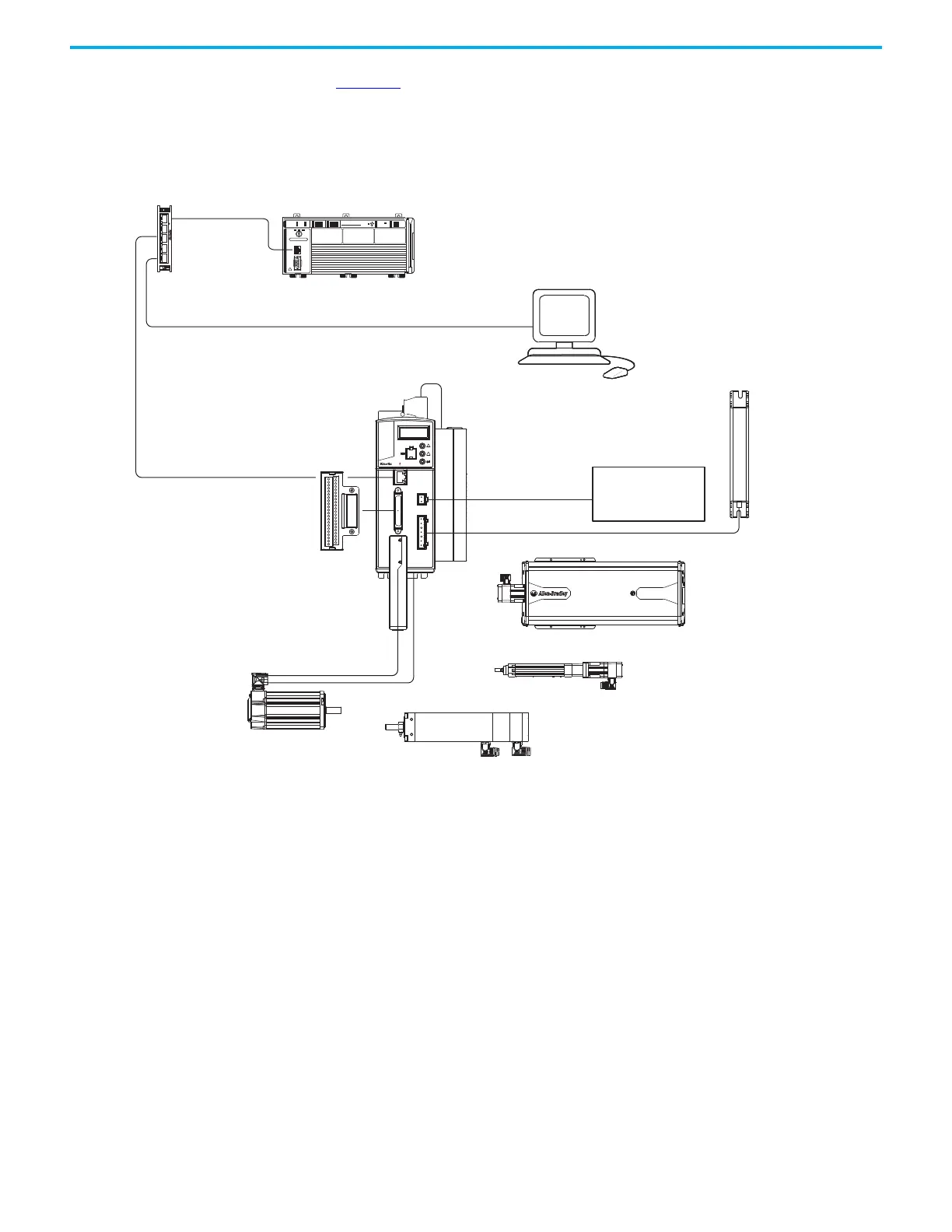
Figure 32 is an example of a typical Kinetix 300 Servo Drive system, in this case
a Kinetix 300 controlled through EtherNet/IP external reference. This
illustrates how the required drive modules and accessories are used in a typical
Kinetix 300 servo drive system.
Figure 32 - Typical Configuration - Kinetix 300 Servo Drive System
CompactLogix L23E
00
3
0 0
2097-V3xxx
Kinetix 300 Drive
Bulletin 2090 or 2097-Fx
AC Line Filter (optional equipment)
2097-F1 Filter Shown
1783-US05T
Stratix® 2000
Switch
CompactLogix Controller Platform
1769-L23E-QB1B Shown
RSLogix 5000
Software
24V DC Control
Back-up Power Supply
(optional equipment)
Kinetix MP and Kinetix TL
Rotary Motors
(MPL-Bxxxx motors shown)
Kinetix 2090
Motor Feedback Cables
Kinetix 2090
Motor Power Cables
1585J-M8CBJM-x
Ethernet (shielded) Cable
2097-TB1 Terminal
Expansion Block
2097-Rx
Shunt Resistor
(optional equipment)
Kinetix MPAR and Kinetix TL Electric Cylinders
(MPAR-Bxxxx electric cylinders shown)
Kinetix MPAS Integrated Linear Stages
(MPAS-B9xxx ballscrew shown)
Kinetix MPAI Heavy Duty Electric Cylinders
(MPAI-Bxxxx electric cylinders shown)
2090-K2CK-D15M
Low-profile Connector Kit
2
3
5
4
1
R
W
P
 Loading...


