Rockwell Automation Publication 2198-RM004C-EN-P - March 2022 23
Chapter 2 Replacement Considerations
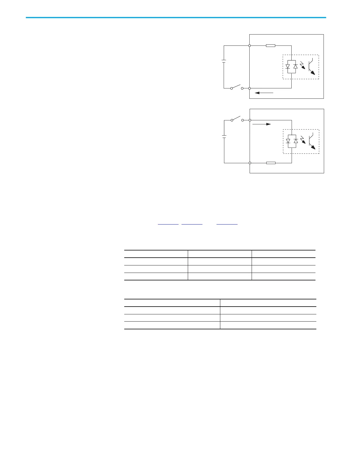
Figure 2 - Kinetix 5100 Drive Digital Input Circuit
Digital Outputs
This section describes the digital outputs for Kinetix 300 and Kinetix 5100
servo drives. Table 23
, Table 24, and Table 25 compare the digital outputs
between the two drive families.
24V DC
INPUTx
DCOM
4.7 kΩ,
approx.
24V DC
INPUTx
DCOM
4.7 kΩ,
approx.
NPN transistor (source mode)
PNP transistor (sink mode)
Kinetix 5100 Servo Drive
Kinetix 5100 Servo Drive
Table 23 - Digital Outputs Comparison
Features Kinetix 300 Kinetix 5100
Outputs 5 6
Brake output assignment Programmable, transistor type Programmable, transistor type
Configurable output assignment Yes Yes
Table 24 - Kinetix 300 Drives Digital Output Signal Specifications
Parameter Value
Scan time 500
μs
Current max 100 mA
Voltage max 30V DC
 Loading...


