22 Rockwell Automation Publication 2198-RM004C-EN-P - March 2022
Chapter 2 Replacement Considerations
The Kinetix 5100 drive digital inputs are assigned to specific functions by
using the KNX5100C software. INPUT9 and INPUT10 are high-speed digital
inputs and registration functionality is supported on these inputs only.
Valid Input functions are shown here:
• Alarm Reset (ARST)
• Clear pulse counter (CCLR)
• Command triggered (CTRG)
• Emergency stop (EMGS)
• Negative Limit (NL)
• Positive Limit (PL)
• Position Selection (POS0… POS6)
• Servo is on (SON, Drive Enable)
• Speed / Position Selection (S-P)
• Speed Selection (SPD0,SPD1)
• Torque mode speed Limit (SPDLM)
• Torque Command (TCM0 TCM1)
• Torque / Position Selection (T-P)
•Torque limit (TRQLM)
See the Programming via Drive Parameters chapter in the Kinetix 5100
Single-axis EtherNet/IP Servo Drives User Manual, publication 2198-UM004
for the full list of digital input functions.
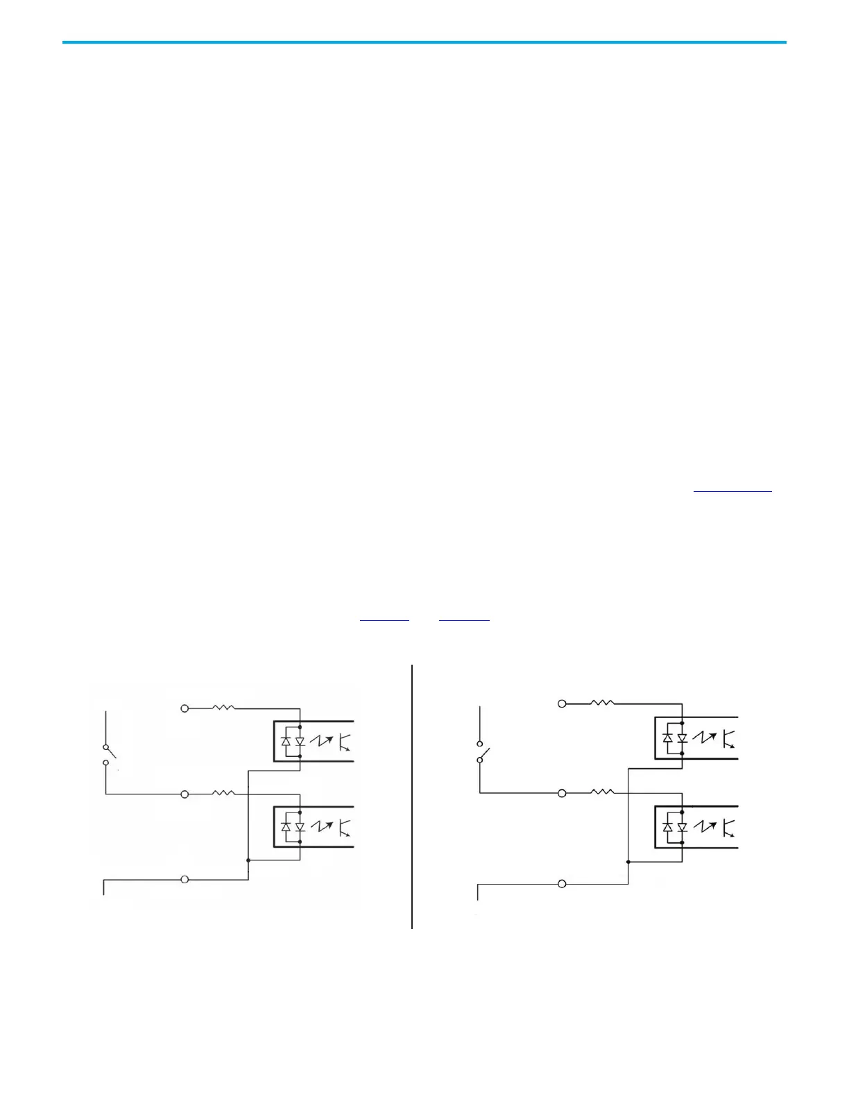
Digital Input Circuits
In both the Kinetix 300 and Kinetix 5100 drives, the digital inputs are optically
isolated. You can configure the inputs for PNP sourcing or NPN sinking as
shown in Figure 1
and Figure 2.
Figure 1 - Kinetix 300 Drive Digital Input Circuit
Sourcing of Digital Inputs
Sinking of Digital Inputs
GND
IN_A2
IN_A_COM
+24V
IN_A1
GND
IN_A2
IN_A_COM
+24V
IN_A1
1.2 kΩ
1.2 kΩ
1.2 kΩ
1.2 kΩ
 Loading...


