Rockwell Automation Publication 2198-RM004C-EN-P - March 2022 43
Chapter 3 Connectors
Auxiliary Feedback There is no separate auxiliary feedback connector used with the Kinetix 300
drive. The auxiliary encoder signal is wired using the I/O connector, see
Table 47
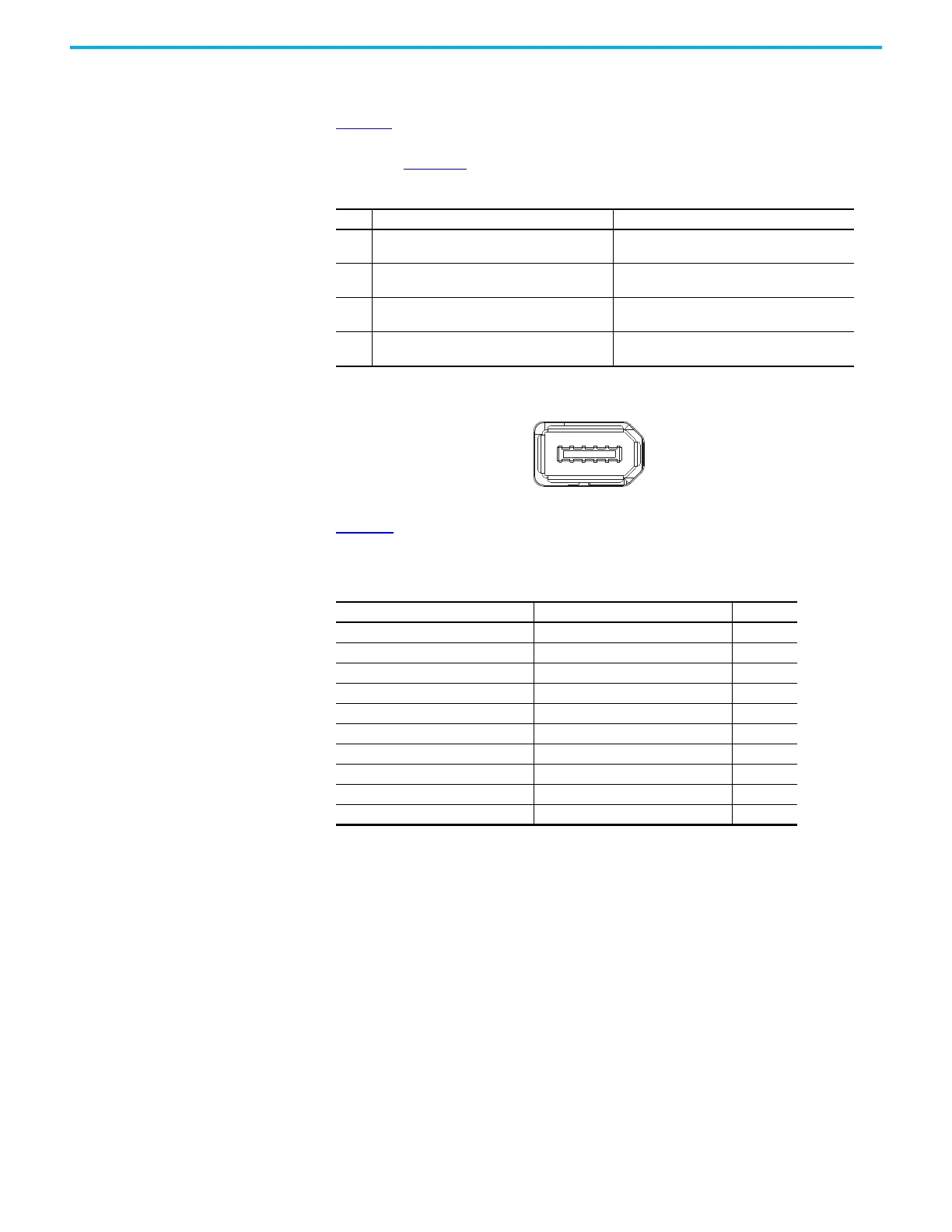
. The Kinetix 5100 uses a 10-pin auxiliary encoder connector, which is
used for wiring a master reference input signal or load feedback encoder,
shown in Figure 16
.
Figure 16 - Kinetix 5100 Drive 10-pin Auxiliary Feedback Connector
Table 48 lists the auxiliary feedback connector pin assignments for the Kinetix
5100 servo drives (AUX connector).
Table 47 - Kinetix 300 Drive Auxiliary Feedback on I/O Connector
Pin Description Signal
1
Sine differential input+
AM+ differential input+
SIN+
AM+
2
Sine differential input-
AM- differential input-
SIN-
AM-
3
Cosine differential input+
BM+ differential input+
COS+
BM+
4
Cosine differential input-
BM- differential input-
COS–
BM–
Table 48 - Kinetix 5100 Auxiliary Feedback Connector Assignment
Signal (Generic TTL Incremental) Description AUX Pin#
MTR_AM+ A Differential Input + 1
MTR_AM- A Differential Input - 2
MTR_BM+ B Differential Input + 3
MTR_BM- B Differential Input - 4
MTR_IM+ Index Differential Input + 5
MTR_IM- Index Differential Input - 6
MTR_ECOM Encoder Common 7
MTR_EPWR5V Encoder 5V Power Output 8
Reserved Reserved 9
Reserved Reserved 10
 Loading...


