Rockwell Automation Publication 2198-RM005A-EN-P - October 2020 27
Chapter 2
Connectors
Connectors on the Kinetix® 350 servo drives and on the Kinetix 5300 servo
drives are of different types in different locations. Make sure that your cables
are long enough to compensate for the differences.
Kinetix 350 Servo Drive
Connector Locations
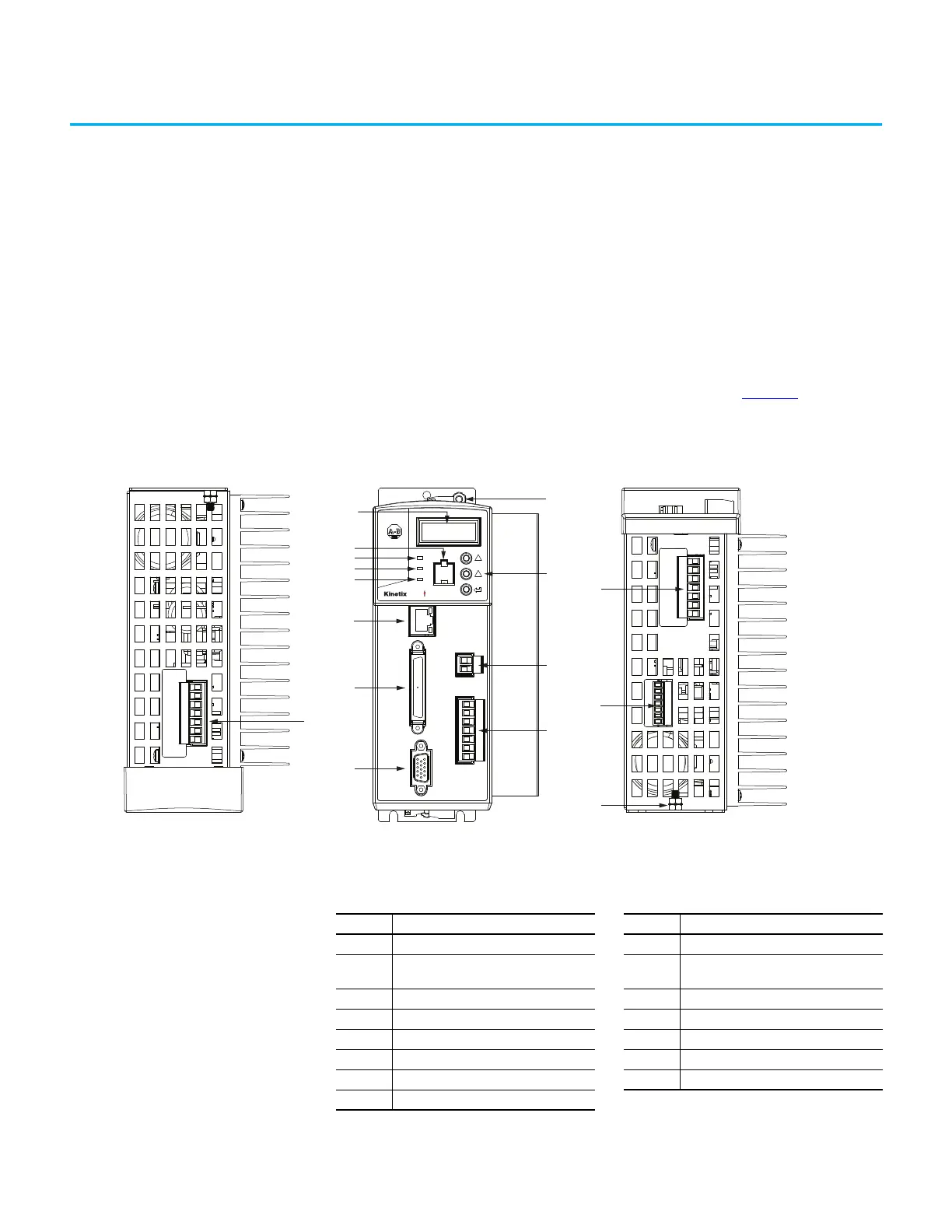
The connectors of the Kinetix 350 servo drives are show in Figure 7. Although
the physical size of the Kinetix 350 drives vary, the location of the connectors
and indicators is identical.
Figure 7 - Kinetix 350 Connector Locations
Kinetix® 350 Drive, Front View
(2097-V33PR5-LM drive is shown)
Kinetix 350 Drive, Bottom View
(2097-V33PR5-LM drive is shown)
Kinetix 350 Drive, Top View
(2097-V33PR5-LM drive is shown)
10
3
4
2
5
6
7
9
8
1
12
13
11
14
15
10
0
3
5 0
Table 24 - Kinetix 350 Drive Connectors
Item Description Item Description
1 Mains (IPD) connector 9 Motor feedback (MF) connector
2
Data status indicator and diagnostic
display
10 Ground lug
3 Memory module socket 11 Shunt resistor and DC bus (BC) connector
4 Network status indicator 12 Back-up power (BP) connector
5 Module status indicator 13 Display control push buttons (3)
6 Axis status indicator 14 Motor power (MP) connector
7 Ethernet communication port (Port 1) 15 Safe torque-off (STO) connector
8 I/O (IOD) connector

 Loading...


