20 Rockwell Automation Publication 2198-RM005A-EN-P - October 2020
Chapter 1 Replacement Considerations
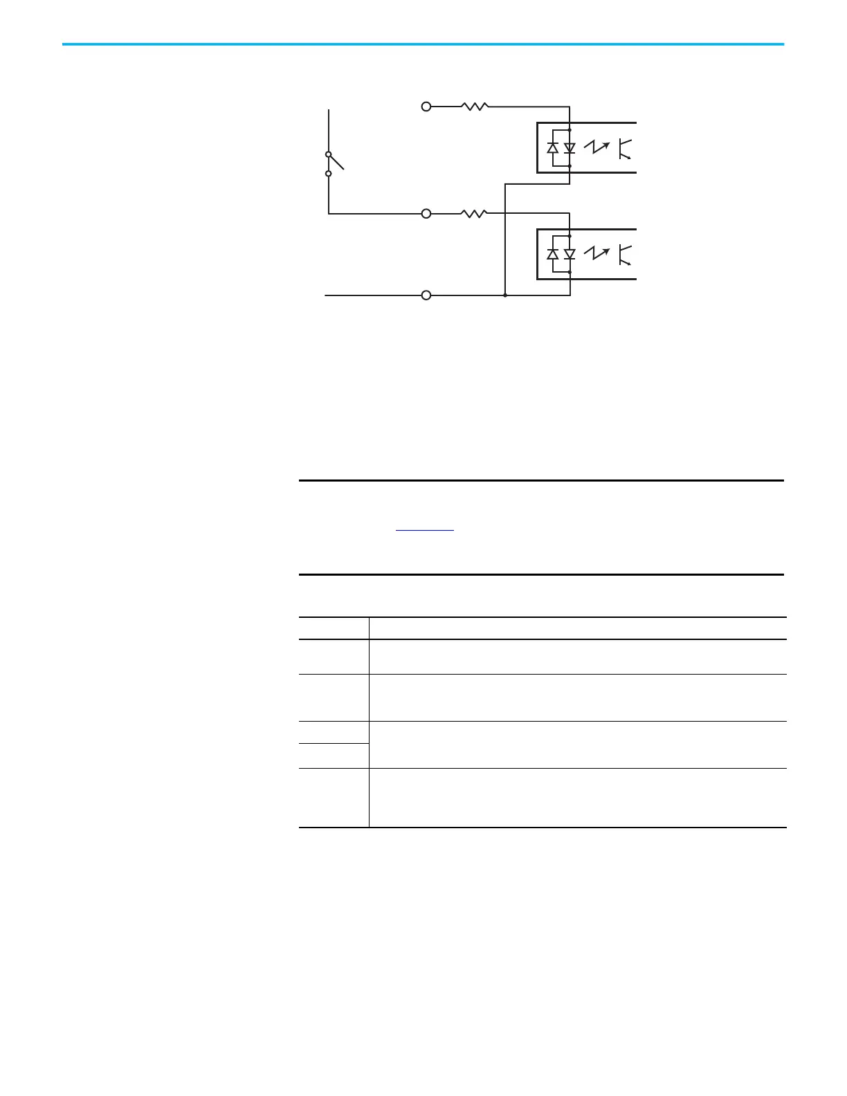
Figure 4 - Sinking of Registration Digital Input
Kinetix 5300 Drives
The Kinetix 5300 drive has four configurable digital inputs and six
configurable functions to choose from in the Logix Designer application.
Digital inputs require a 24V DC @ 15 mA supply. These are sinking inputs that
require a sourcing device. A common and cable shield connection is provided
on the connector for digital inputs.
Table 17 - Understand Digital Input Functions
Motor Brake Output
The Kinetix 350 and 5300 drives both have an optional motor brake output. The
brake option is a spring-set holding brake that releases when voltage is applied
to the brake coil in the motor. The customer-supplied 24V power supply drives
the brake output through a solid-state relay.
GND
REG
REG_COM
+24V
REG
1.2 kΩ
1.2 kΩ
IMPORTANT To improve registration input EMC performance, refer to the System
Design for Control of Electrical Noise Reference Manual, publication
GMC-RM001
.
Although any input can be configured as a registration input, only two
can be registration inputs at any one time
Function Description
Enable
A 24V DC input is applied to this terminal to move the AxisCipDrive from Start-Inhibited to
Stopped State.
Home
An active state indicates to a homing sequence that the referencing sensor has been seen.
Typically, a transition of this signal is used to establish a reference position for the machine
axis.
Registration 1 An inactive-to-active transition (also known as a positive transition) or active-to-inactive
transition (also known as a negative transition) is used to latch position values for use in
registration moves.
Registration 2
Positive
overtravel
Negative
overtravel
The positive/negative limit switch (normally closed contact) inputs for each axis require 24V DC
(nominal).

 Loading...


