30 Rockwell Automation Publication 2198-RM005A-EN-P - October 2020
Chapter 2 Connectors
The Kinetix 5300 drive has four configurable digital inputs and six
configurable functions to choose from in the Studio 5000 Logix Designer®
application.
Table 28 - Kinetix 5300 Drive Configurable Functions
Motor Feedback
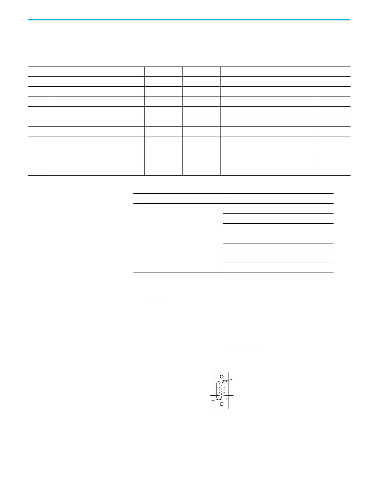
The Table 29 compares the motor feedback connector pinouts for the
Kinetix 350 (motor feedback connector) and Kinetix 5300 servo drives (MFB
connector).
Refer to the Kinetix 350 Single-axis EtherNet/IP Servo Drives User Manual,
publication 2097-UM002
and the Kinetix 5300 Single-axis EtherNet/IP Servo
Drives User Manual, publication 2198-UM005
for additional information on
supported feedback types.
Figure 9 - 15 Pin Motor Feedback Connector Pin Assignment
Table 27 - Kinetix 5300 Drive I/O and Auxiliary Feedback Connector Assignment
Pin Description Signal Pin Description Signal
1 24V current-sinking fast input #1 IN1 11 24V current-sinking fast input #3 IN3
2 I/O common for customer-supplied 24V supply COM 12 I/O common for customer-supplied 24V supply COM
3 24V current-sinking fast input #2 IN2 13 24V current-sinking fast input #4 IN4
4 I/O common for customer-supplied 24V supply COM 14 I/O common for customer-supplied 24V supply COM
5 I/O cable shield termination point SHLD 15 I/O cable shield termination point SHLD
6 Channel AM Differential Input + AM+ 16 Channel AM Differential Input – AM–
7 Channel BM Differential Input + BM+ 17 Channel BM Differential Input – BM–
8 Channel IM Differential Input + IM+ 18 Channel IM Differential Input – IM–
9 Encoder 5V power output AUX_EPWR_5V 19 Auxiliary common AUX_COM
10 I/O cable shield termination point SHLD 20 I/O cable shield termination point SHLD
Default Configuration Description
Digital input1= Enable
Digital input2 = Home
Digital input3 = Registration 1
Digital input4 = Registration 2
0 = Unassigned
1 = Enable
2 = Home
3 = Registration 1
4 = Registration 2
5 = Positive overtravel
6 = Negative overtravel
Pin 15
Pin 11
Pin 6
Pin 1
Pin 5
Pin 10

 Loading...


