Rockwell Automation Publication 2198-RM005A-EN-P - October 2020 37
Dimensions, Cables, and Wiring Chapter 3
The existing motor power cables can be used for the Kinetix MP motors since
they are supported by both the Kinetix 350 drives and the Kinetix 5300 drives.
The existing motor feedback cables can be used for the Kinetix MP motors
since they are supported by both the Kinetix 350 drives and the Kinetix 5300
drives. However, if flying lead cables were used on the Kinetix 350 drive, the
feedback connector kit will need to be replaced by 2198-K53CK-D15M feedback
connector kit, as it is required for Kinetix 5300 drives.
Factory-made motor power and feedback cables with premolded connectors
are designed to minimize electromagnetic interference (EMI).
Rockwell Automation recommends factory-made cables to achieve the
expected system performance.
For details and drawings of recommended cables see the Kinetix Motion
Accessories Specifications Technical Data, publication KNX-TD004
, the bill of
materials (BOM) configuration tool within Motion Analyzer, or
ProposalWorks™ from Rockwell Automation.
Power Wiring
Use these power wiring examples to assist you in comparing the power wiring
for the Kinetix 350 servo drives and the Kinetix 5300 servo drives.
Kinetix 350 Power Wiring Diagrams
This section contains examples of typical single-phase and three-phase facility
input power that is wired to single-phase and three-phase Kinetix 350 drives.
The grounded power configuration lets you ground your single-phase or three-
phase power at a neutral point.
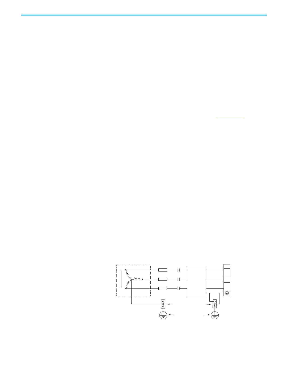
Three-phase Power Wired to Three-phase Drives
These examples illustrate grounded three-phase power that is wired to three-
phase Kinetix 350 drives when phase-to-phase voltage is within drive
specifications.
Figure 14 - Three-phase (400/480V) Power Configuration (WYE Secondary)
L3
L2
L1
IPD
L3
L2
L1
E
L3
L2
L1
L3
L2
L1
Transformer (WYE) Secondary
Kinetix 350 Drives
Three-phase AC Input
Bonded Cabinet Ground Bus
Ground Grid or
Power Distribution Ground
AC Line
Filter
M1
Contactor
Input Fusing
Feeder and branch short circuit
protection is not illustrated.
2097-V34PRx-LM

 Loading...


