32 Rockwell Automation Publication 2198-RM005A-EN-P - October 2020
Chapter 2 Connectors
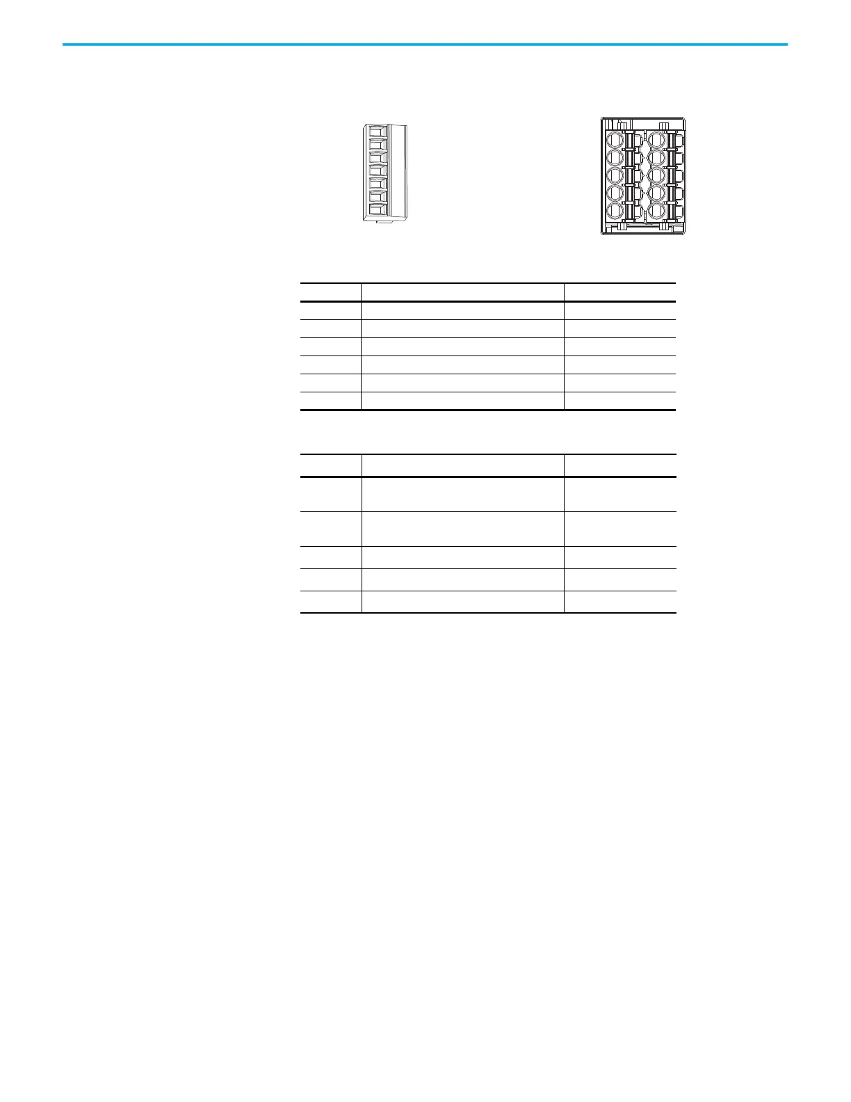
Figure 10 - STO Connector Assignment Comparison
Table 30 - Kinetix 350 STO Connector Assignment
STO Pin Description Signal
1 +24V DC output from the drive +24V DC control
2 +24V DC output common Control COM
3 Safety status Safety Status
4 Safety input 1 (+24V DC to enable) Safety Input 1
5 Safety common Safety COM
6 Safety input 2 (+24V DC to enable) Safety Input 2
Table 31 - Kinetix 5300 STO Connector Assignment
STO Pins Description Signal
1 and 6 Safety bypass plus signal. Connect to both
safety inputs to disable the STO function
SB+
2 and 7 Safety bypass minus signal. Connect to
safety common to disable the STO function
SB-
3 and 8 STO input 1 (SS_IN_CH0) S1
4 and 9 STO input common (SCOM) SC
5 and 10 STO input 2 (SS_IN_CH1) S2
Kinetix 350 Drive
STO Connector
Kinetix 5300 Drive
STO Connector
Pin 1
SB+
SB-
S1
SC
S2
Pin 5

 Loading...


