50 Rockwell Automation Publication MOTION-AT007A-EN-P - May 2020
Chapter 5 Regenerative Bus Supply Configurations With Active Shunt
Input and Output Signals
For the Kinetix 7000 drives, wire the control and interface signals on the General Purpose Relay (GPR) and General Purpose I/O (GPIO)
connectors as described in the following tables. See the Kinetix 7000 Servo Drives User Manual, publication 2099-UM001
, for more
information on the terminal block connections.
In common bus configurations, a REGEN connection on the General Purpose I/O connector is also required for the drives. This connection
must be wired in series to the control string, and also wired from the regenerative bus supply to the Kinetix 7000 drive to indicate bus
voltage is present.
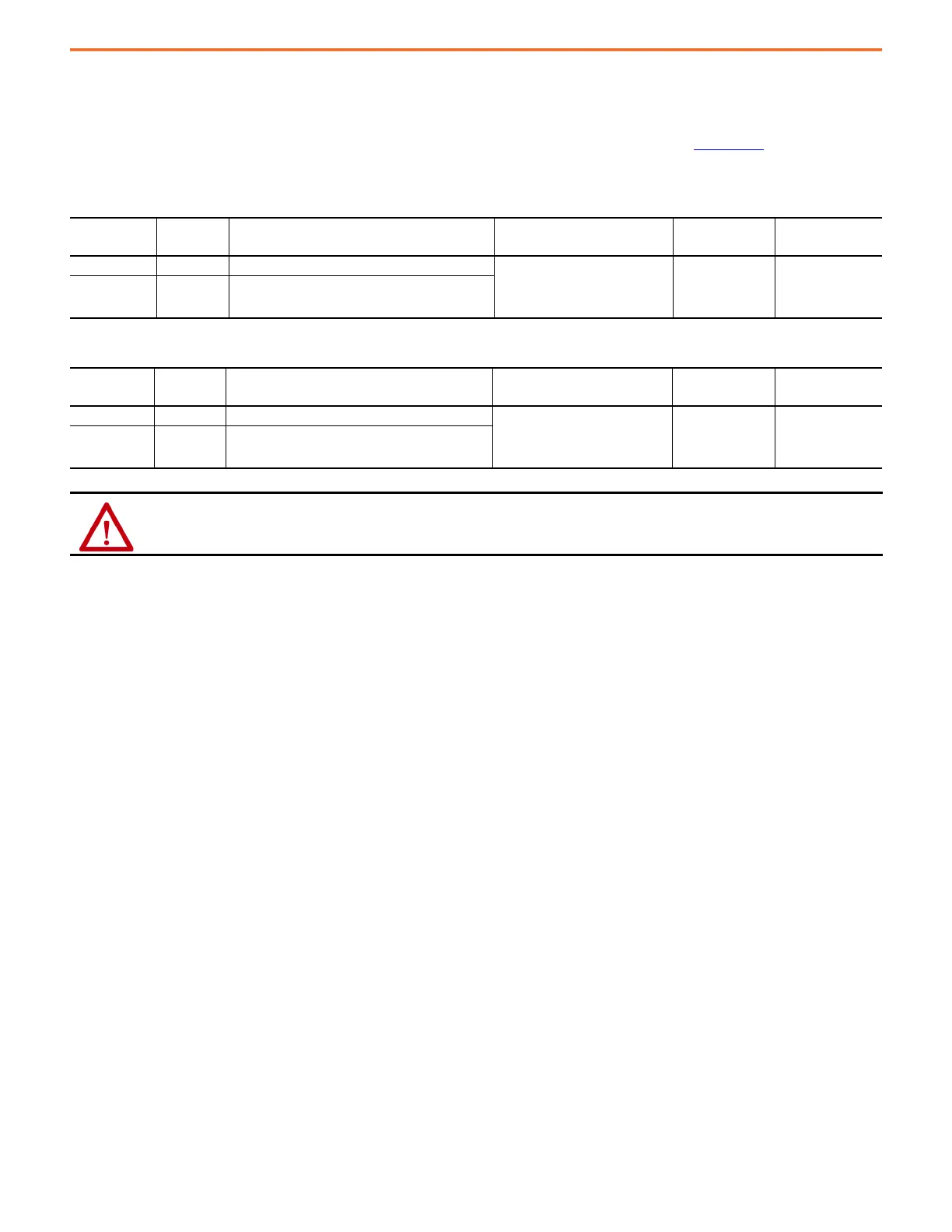
Table 37 - General Purpose Relay Connections
Signal Terminal Description
Recommended Wire Size
mm
2
(AWG)
Strip Length
mm (in.)
Torque Value
N•m (lb•in)
DRIVE OK+ 5 Programmable N.O. Relay 2 output 0.75 (18)
(stranded wire with ferrule)
1.5 (16)
(solid wire)
7.0 (0.275) 0.235 (2.0)
DRIVE OK- 6 Programmable Relay 2 common
Table 38 - General Purpose I/O Connections
Signal Terminal Description
Recommended Wire Size
mm
2
(AWG)
Strip Length
mm (in.)
Torque Value
N•m (lb•in)
Regen_OK+ 7 Regenerative power supply status 0.75 (18)
(stranded wire with ferrule)
1.5 (16)
(solid wire)
7.0 (0.275) 0.235 (2.0)
Regen_OK- 8 Regenerative power supply status common
ATTENTION: For the Kinetix 7000 drives, wiring the DRIVE OK signal on the General Purpose Relay is required. To avoid injury or
damage to the drive, wire the DRIVE OK relay into your control string.

 Loading...


