Rockwell Automation Publication MOTION-AT007A-EN-P - May 2020 51
Regenerative Bus Supply Configurations With Active Shunt Chapter 5
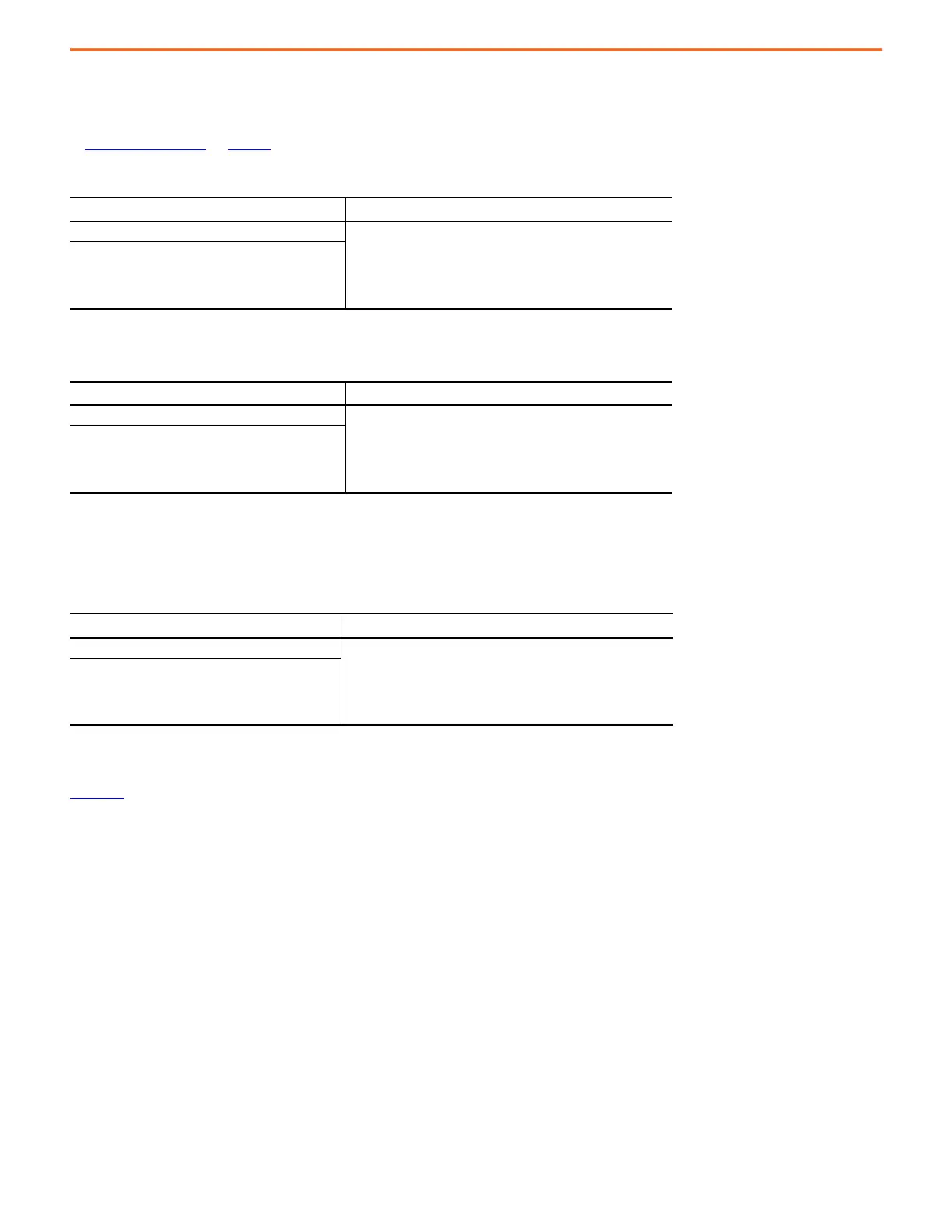
Drive Ground Jumper Settings
Set the ground jumpers for the Kinetix 6000 (400V-class), Kinetix 6200/6500, and Kinetix 7000 drives according to the following tables. Refer
to Additional Resources
on page 81 for the user manual with instructions on how to set the ground jumpers/screws for your servo drive.
PowerFlex 750-Series drives contain protective metal-oxide varistors (MOV) and common mode capacitors referenced to ground. To guard
against unstable operation and/or damage, the drive must be properly configured as shown in the following table.
For instructions on how to disconnect the PE jumpers, refer to PowerFlex 750-Series Power Jumpers Installation Instructions, publication
750-IN011
.
Table 39 - Ground Jumper Settings for Kinetix 6000 (400V-class) and Kinetix 6200/6500 Drives
Ground Configuration
Ground Jumper Setting
(1)
(1) When powered by 2198-RPxxx regenerative bus supply.
Grounded (wye)
Set for ungrounded power
•AC-fed ungrounded
• Corner grounded
• Impedance grounded
• DC-bus from active converter
Table 40 - Ground Jumper Settings for Kinetix 7000 Drives
Ground Configuration
Ground Jumper Setting
(1)
(1) When powered by 2198-RPxxx regenerative bus supply.
Grounded (wye)
Removed
•AC-fed ungrounded
• Corner grounded
• Impedance grounded
• DC-bus from active converter
Table 41 - Power Jumper Settings for PowerFlex 750-Series Drives (Frames 1…6)
Ground Configuration
Ground Jumper Setting
(1)
(1) When powered by 2198-RPxxx regenerative bus supply.
Grounded (wye)
• Jumper PE-A disconnected (MOV/input filter caps)
• Jumper PE-B disconnected (DC-bus common mode caps)
•AC-fed ungrounded
• Corner grounded
• Impedance grounded
• DC-bus from active converter

 Loading...


