142 Rockwell Automation Publication D2-3518-4 - January 2020
Chapter 9 Parameter Descriptions
Figure 67 - Anlg Out Absolute (341)
Selects the source of the value that drives the user-configurable analog output.
See AC Line I/O Board Description (Frame 3 Only)
on page 25 through
Combined I/O Board Description (Frame 4 Only)
on page 29 for a description
of I/O hardware that is present on this drive and is controlled by the inverter.
Sets the user-configurable analog output value when the source value is at
maximum.
See AC Line I/O Board Description (Frame 3 Only)
on page 25 through
Combined I/O Board Description (Frame 4 Only)
on page 29 for a description
of I/O hardware that is present on this drive and is controlled by the inverter.
342
Analog Out1 Sel
Range: 0 = Output Freq
1 = Command Freq
2 = Output Amps
3 = Torque Amps
4 = Flux Amps
5 = Output Power
6 = Output Volts
7 = DC Bus Volts
8 = PI Reference
9 = PI Feedback
10 = PI Error
11 = PI Output
12 = %Motor OL
13 = %Drive OL
14 = Application
Default: 14 = Application
Access: 0 Path: Inputs & Outputs > Analog Outputs
See also: 1...7, 12, 135...138, 219, 220
343
Analog Out1 Hi
Range: 4.000...20.000 mA [0.001 mA]
-/+10.000V [0.1V]
0.0...10.000V [0.1V]
Default: 20.0 mA
Access: 0 Path: Inputs & Outputs > Analog Outputs
See also: 31, 342
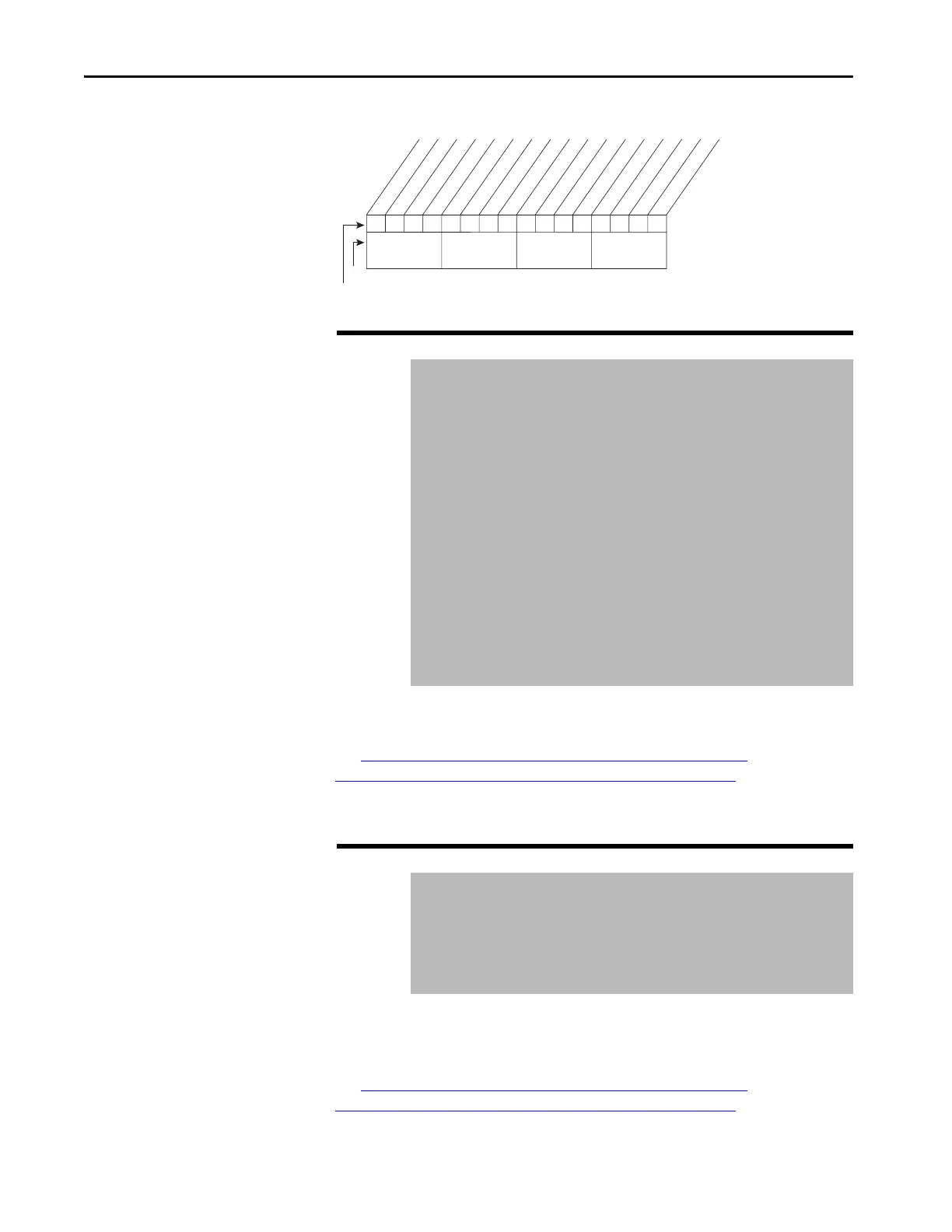
xxx0xxxxxxxxxxxx
0011234567891112131415
1 =Enabled
0=Disabled
x =Reserved
Bit #
Factory Default Bit Values
Analog Out1
Nibble 1Nibble 2Nibble 3Nibble 4
 Loading...


