26 Rockwell Automation Publication 750-RM004A-EN-P - April 2018
Chapter 1 Selection Considerations
EMI Filters
The PowerFlex 755TL/TR drive standard EMI filtering is obtained by
selecting catalog code (-L) or (-M) in catalog position ‘g’. Additional EMI
filtering can be supplied by specifying catalog code (-J) or (-K) in catalog
position ‘g’. The (-J) and (-K) option codes add ferrite cores to AC lines after
the precharge circuits.
If option code (-J) or (-K) EMI filtering is required for EMC compliance, then
CM jumper PE-B1 may need to be connected (IN). See Power Filter Jumpers
on page 26 and the PowerFlex 750-Series Products with TotalFORCE Control
installation instructions, publication 750-IN100
, for more information about
power filter jumper settings.
Power Filter Jumpers
The power filter jumper configuration of the new PowerFlex 755TL/TR,
PowerFlex 755TM common bus inverters is an important part of your
migration.
See PowerFlex 750-Series Products with TotalFORCE Control installation
instructions, publication 750-IN100
for detailed information about the use
and location of the power filter jumpers.
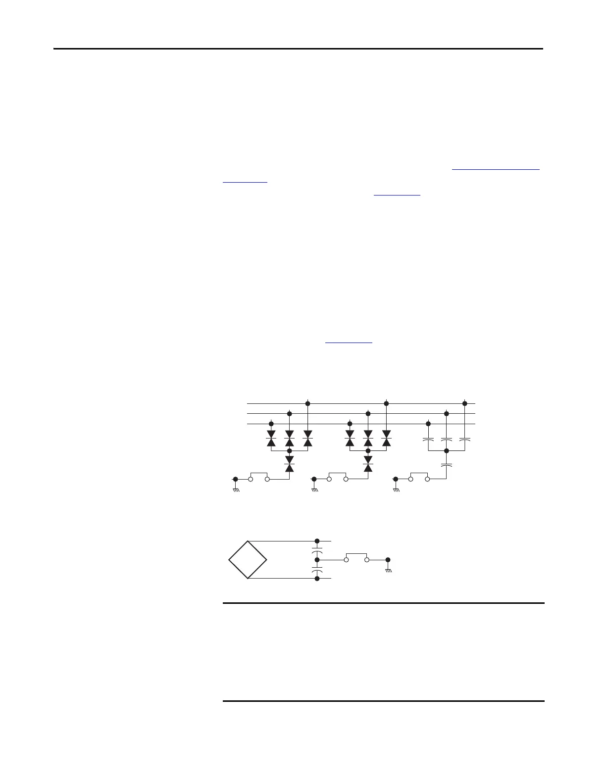
Figure 2 - PowerFlex 755T Power Jumpers
IMPORTANT Unless equipped with power option code -P51 (Marine Bus Conditioner), the
default factory settings for the power filter jumpers is; PE-A, PE-A1, PE-A2
jumpers in the connected (IN) position and the PE-B1 jumper in the
disconnected (OUT) position. If necessary, reconfigure the power filter
jumpers as required by the power source grounding method and EMC
requirements. When the -P51 option is selected, the factory jumper settings
change.
MOV and AC Common Mode Capacitor
DC Common Mode Capacitor
• PE-A, MOV on the AC precharge circuit board
• PE-A1, MOV on the TVSS module
• PE-A2, Common Mode Capacitors on the AC
Common Mode Filter circuit board
• PE-B1, Common Mode Capacitors on the Line
Side Power Interface circuit boards
• PE-A, PE-A1, PE-A2 not used with PowerFlex
755TM common bus inverters
R/L1
S/L2
T/L3
PE–A1
4
PE–A2
PE–A
DC+
 Loading...


