88 Rockwell Automation Publication 750-RM004A-EN-P - April 2018
Chapter 1 Selection Considerations
PowerFlex 755T I/O Option Modules
The PowerFlex 755T product main control board has one digital input that is
typically used for hardware ENABLE. Optional 750-Series I/O modules must
be added if additional digital and analog I/O is required.
Refer to the PowerFlex 750-Series Products with TotalFORCE Control
installation instructions, publication 750-IN100
, for detailed information
about option modules.
Chapter 2 Control Devices shows an example of using a 20-750-2263C-1R2T,
24V DC I/O module to emulate a typical hardware control function used with
a PowerFlex 700S drive.
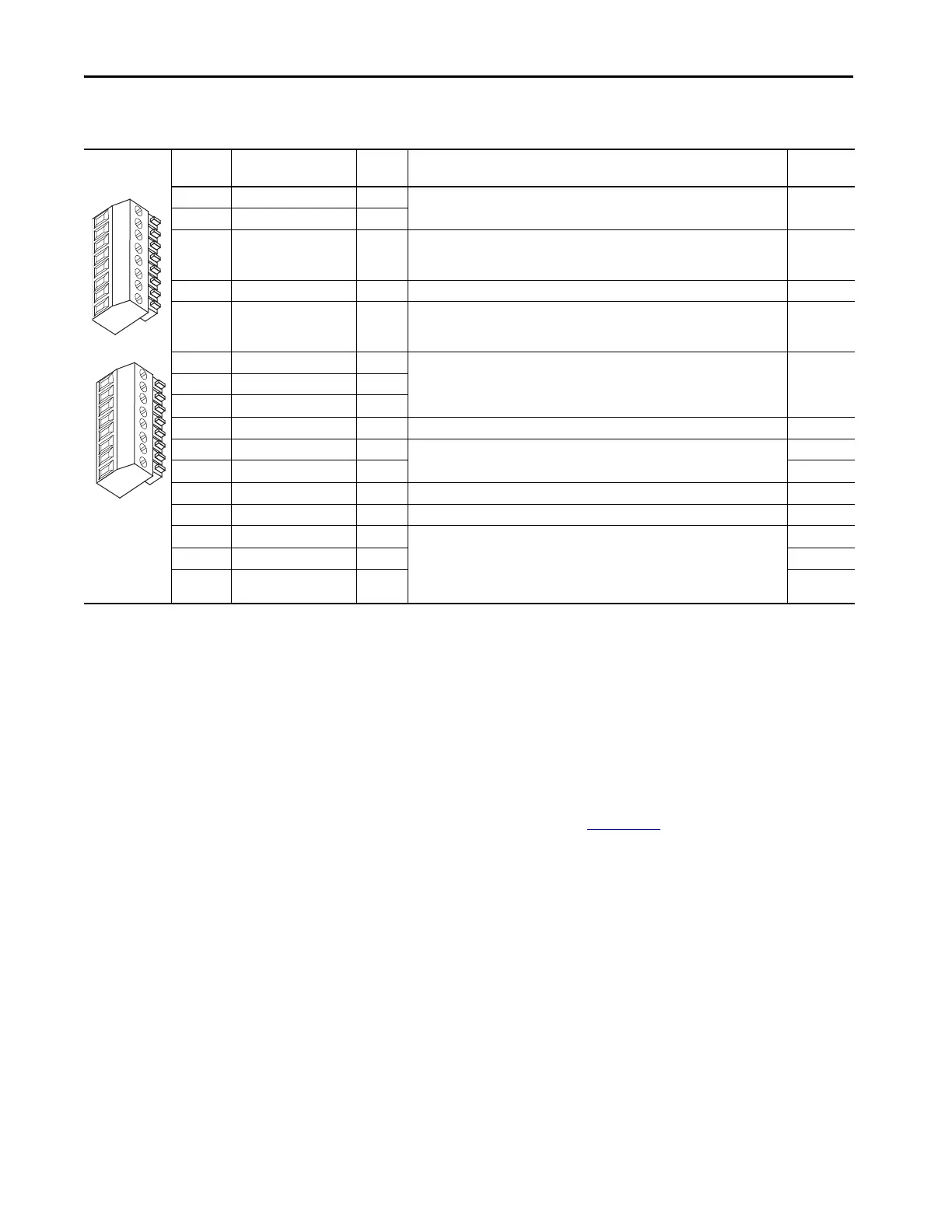
Table 46 - PowerFlex 700S TB2 Control Terminals
Terminal Signal Factory
Default
Description Related
Parameter
1 24V DC Common (-) NA Drive supplied 24V DC logic input power
Rating: 300 mA maximum load
2 24V DC Source (+) NA
3 Digital Output 1 24V DC Open Collector (sinking logic)
Rating: Internal Source = 150 mA max.
External Source = 750 mA
816, 847
4 Digital Output 1/2 Com NA Common for Digital Output 1 & 2
5 Digital Output 2 24V DC Open Collector (sinking logic)
Rating: Internal Source = 150 mA max.
External Source = 750 mA
851, 852
6 Relay Output 3 (NC) Relay contact output
Rating: 115V AC or 24V DC = 2 A max.
Inductive/Resistive
856, 857
7Relay Output 3 ComNA
8Relay Output 3 (NO)
9 Digital Input 1-3 Com NA Common for Digital Inputs 1-3
10 Digital Input 1 High speed 12V or 24V DC
(1)
, sinking
Load:15 mA at 24V DC
825
11 Digital Input 2 826
12 Digital Input 3 Load:15 mA at 24V DC sourcing 827
13 Digital Input 4-6 Com NA Common for Digital Inputs 4-6
14 Digital Input 4 Load: 10 mA at 24V DC sinking/sourcing
Load: 7.5 mA at 115V AC
Note: The 115V AC Digital Inputs can withstand 2 mA of leakage current without turning on. If an
output device has a leakage current greater than 2 mA, a burden resistor is required. A 68.1 K
resistor with a 0.5 W rating should be used to keep the 115V AC output below 2 mA.
828
15 Digital Input 5 829
16 Digital Input 6 HW
Enable
830
(1) Digital Inputs 1 and 2 are configured for 12V or 24V DC via DIP switches S3-1 and S3-2, respectively. 24V DC is the default setting.
 Loading...


