78 Rockwell Automation Publication 750-RM004A-EN-P - April 2018
Chapter 1 Selection Considerations
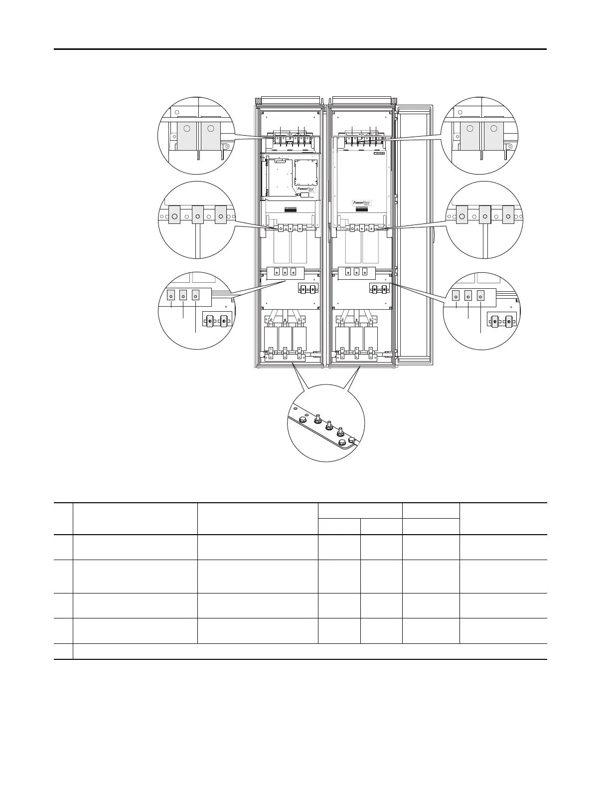
Figure 15 - PowerFlex 700S Frame 12 Power Terminal Locations
DANGER DANGER
DC BUS CONDUCTORS AND CAPACITORS
OPERATE AT HIGH VOLTAGE. REMOVE POWER
AND WAIT 5 MINUTES BEFORE SERVICING
DANGER DANGER
DC BUS CONDUCTORS AND CAPACITORS
OPERATE AT HIGH VOLTAGE. REMOVE POWER
AND WAIT 5 MINUTES BEFORE SERVICING
Cat No.
1234567890-*
FIELD INSTALLED OPTIONS:FIELD INSTALLED OPTIONS:
DC- DC+ DC- DC+
1L1
1L2
1L3
2L1
2L2
2L3
1U/T1
1V/T2
1W/T3
2U/T1
2V/T2
2W/T3
Enclosure Style A Shown
1155
3
2 2
4 4
Table 42 - PowerFlex 700S Frame 12 Power Terminal Specifications
No. Name Description Wire Size Range
(1)(2)
Torque Terminal Bolt Size
(3)(4)
Maximum Minimum Recommended
1 Input Power Terminal Block
(3)
1L1, 1L2, 1L3, 2L1, 2L2, 2L3
Input power 300 mm
2
(600 MCM)
2.1 mm
2
(14 AWG)
40 N•m
(354 lb•in)
M12
2 Output Power Terminal Block
(3)
1U/1T1, 1V/1T2, 1W/1T3,
2U/2T1, 2V/2T2, 2W/2T3
Motor connections 300 mm
2
(600 MCM)
2.1 mm
2
(14 AWG)
40 N•m
(354 lb•in)
M12
3 SHLD Terminal, PE, Motor Ground
(3)
Terminating point for wiring shields 300 mm
2
(600 MCM)
2.1 mm
2
(14 AWG)
40 N•m
(354 lb•in)
M10
4 DC Bus
(3)
(2 Terminals; DC–, DC+)
DC input or external brake 300 mm
2
(600 MCM)
2.1 mm
2
(14 AWG)
40 N•m
(354 lb•in)
M12
5 Cable Clamp for Shield
(1) Maximum/minimum sizes that the terminal block will accept - these are not recommendations.
(2) Do Not exceed maximum wire size. Parallel connections may be required.
(3) These connections are Busbar type terminations and require the use of lug type connectors.
(4) Apply counter torque to the nut on the other side of terminations when tightening or loosening the terminal bolt to avoid damage to the terminal.
 Loading...


