80 Rockwell Automation Publication 750-RM004A-EN-P - April 2018
Chapter 1 Selection Considerations
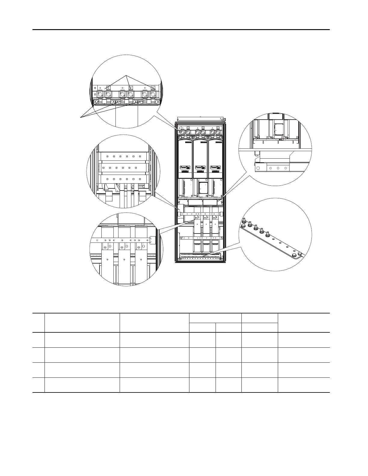
Figure 17 - PowerFlex 700S Frame 14 Power Terminal Locations
U/T1
V/T2 W/T3
Side View
U/T1
V/T2 W/T3
L3
L1
L2
Ground Terminals
DC Bus Terminals
Output Power Terminals
without du/dt Filters
Output Power Terminals
with du/dt Filters
Input Power
Terminals
DC–
(Front Terminals)
DC+
(Back Terminals)
Center Enclosure Shown
4
1
2
3
2
Table 44 - PowerFlex 700S Frame 14 Power Terminal Specifications
No. Name Description Wire Size Range
(1)(2)
Torque Terminal Bolt Size
(3)(4)
Maximum Minimum Recommended
1 Input Power Terminal Block
(1)
L1, L2, L3
Input power 300 mm
2
(600 MCM)
2.1 mm
2
(14 AWG)
40 N
•m
(354 lb
•in)
M12
2 Output Power Terminal Block
(3)
U/T1, V/T2, W/T3
Motor connections 300 mm
2
(600 MCM)
2.1 mm
2
(14 AWG)
40 N•m
(354 lb•in)
M12
3 SHLD Terminal, PE, Motor Ground
(3)
Terminating point for wiring shields 300 mm
2
(600 MCM)
2.1 mm
2
(14 AWG)
40 N•m
(354 lb•in)
M10
4 DC Bus
(3)
(3 Terminals; DC–, DC+)
DC input or external brake 300 mm
2
(600 MCM)
2.1 mm
2
(14 AWG)
40 N•m
(354 lb•in)
M12
(1) Maximum/minimum sizes that the terminal block will accept - these are not recommendations.
(2) Do Not exceed maximum wire size. Parallel connections may be required.
(3) These connections are Busbar type terminations and require the use of lug type connectors.
(4) Apply counter torque to the nut on the other side of terminations when tightening or loosening the terminal bolt in order to avoid damage to the terminal.
 Loading...


