1-2 General Installation Information
If any or all of these conditions exist, it is recommended that the user install
a minimum amount of impedance between the drive and the source. This
impedance could come from the supply transformer itself, the cable
between the transformer and drive or an additional transformer or reactor.
The impedance can be calculated using the information supplied in either
the PowerFlex Reference Manual or the technical document on Wiring and
Grounding Guidelines, publication DRIVES-IN001.
General Grounding
Requirements
The drive Safety Ground - PE must be connected to system ground.
Ground impedance must conform to the requirements of national and local
industrial safety regulations and/or electrical codes. The integrity of all
ground connections should be periodically checked.
For installations within a cabinet, a single safety ground point or ground bus
bar connected directly to building steel should be used. All circuits
including the AC input ground conductor should be grounded
independently and directly to this point/bar.
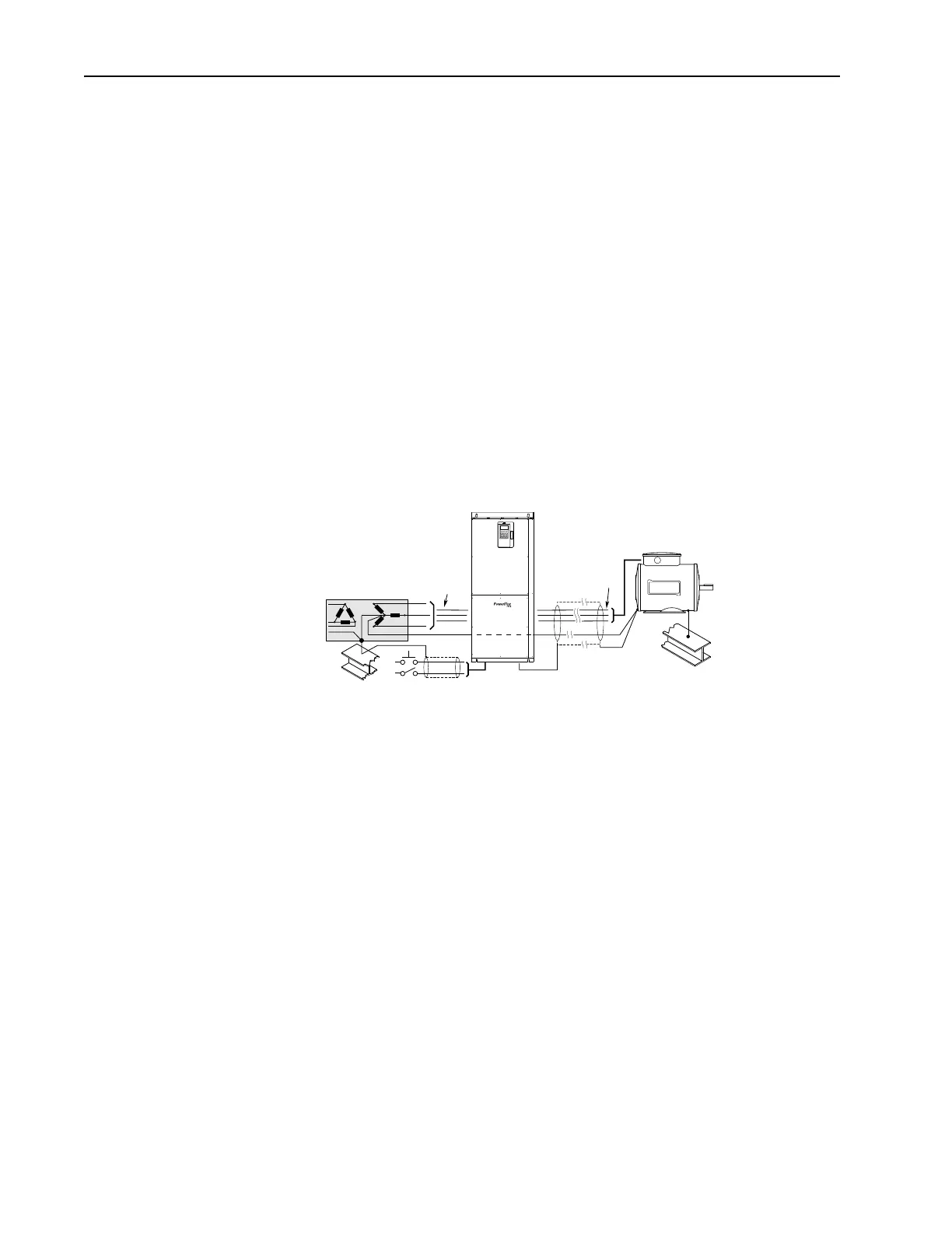
Table 1.A Typical Grounding
Safety Ground - PE
This is the safety ground for the drive that is required by code. This point
must be connected to adjacent building steel (girder, joist), a floor ground
rod or bus bar (see above). Grounding points must comply with national and
local industrial safety regulations and/or electrical codes.
Shield Termination - SHLD
The Shield terminal provides a grounding point for the motor cable shield.
It must be connected to an earth ground by a separate continuous lead. The
motor cable shield should be connected to this terminal on the drive (drive
end) and the motor frame (motor end). A shield terminating cable gland
may also be used.
When shielded cable is used for control and signal wiring, the shield
should be grounded at the source end only, not at the drive end.
U (T1)
V (T2)
W (T3)
R (L1)
S (L2)
T (L3)
PE
SHLD
 Loading...


