7-10 Frame 11 Installation
Power Wiring
400 and 480 Volt AC Input Wiring for Frame 11 Drives
Frame 11 drives with 400V and 480V AC input power utilize two parallel
input rectifying modules, and therefore have two sets of AC input power
terminals. You must supply power to both sets of input terminals. There are
several methods for accomplishing this.
Important: Parallel wiring must have the same cable dimensions, type and
routing. Non-symmetrical wiring may cause unequal loading
between the converters and reduce the drive’s ability to deliver
current to the motor.
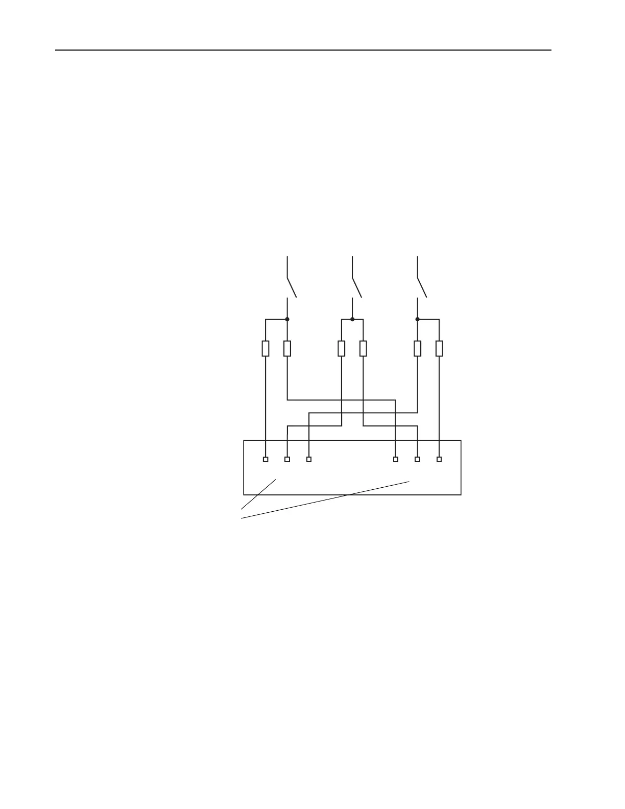
Figure 7.1 Frame 11 AC Wiring Example: Two Fuses per Phase
1L1
1L2
1L3
2L1
2L2
2L3
L1 L2 L3
AC Input Power Terminals
Inside Drive
AC Input Power Wiring, Fuses, and
Disconnect Device Provided by
Customer
 Loading...


