EasyManuals Logo

Rockwell Automation Allen-Bradley PowerFlex 700S Installation Manual

Rockwell Automation Allen-Bradley PowerFlex 700S
113 pages
To Next Page IconTo Next Page
To Previous Page IconTo Previous Page
Page #43 background imageLoading...
Page #43 background image
PowerFlex 700S Control Wiring 3-15
Auxiliary Power Supply
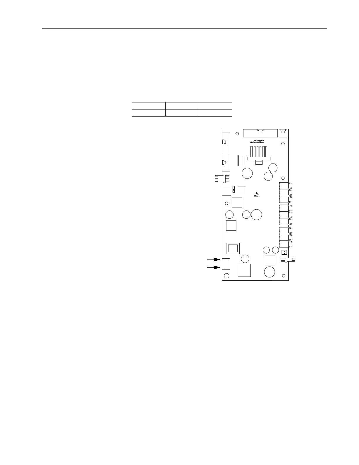
You may use an auxiliary power supply to keep the 700S Control Assembly
energized, when input power is de-energized. This allows the Main Control
Board, DriveLogix controller and any feedback option cards to continue
operation. Connect auxiliary power to J15 on the High Power Interface
board. You must set parameter 153 [Control Options] / bit 17 [Aux Pwr
Sply] to enable this feature.
Table 3.H Auxiliary Power Supply Specifications
Voltage Current (Min) Power (Min)
24V dc ± 5% 3A 75W
J15 Auxiliary
Power Connector
Pin 1 (24V dc power)
Pin 3 (24V dc common)
High Power
Interface Board

Table of Contents

Other manuals for Rockwell Automation Allen-Bradley PowerFlex 700S

Questions and Answers:

Question and Answer IconNeed help?

Do you have a question about the Rockwell Automation Allen-Bradley PowerFlex 700S and is the answer not in the manual?

Rockwell Automation Allen-Bradley PowerFlex 700S Specifications

General IconGeneral
BrandRockwell Automation
ModelAllen-Bradley PowerFlex 700S
CategoryController
LanguageEnglish

Related product manuals