Frame 11 Installation 7-9
Ungrounded and
Unbalanced Installations
Frame 11 drives are equipped with common mode capacitors that are
referenced to ground. To guard against drive damage, these capacitors
should be disconnected if the drive is installed on an ungrounded
distribution system. To disconnect the capacitors, move the two jumpers as
shown below. Refer to publication PFLEX-RM001, PowerFlex Reference
Manual, for information on ungrounded system installation.
The jumpers are located on the Rectifying Modules, which are on the center
and right-hand power stacks of the drive’s power structure. Refer to Moving
Control Frame on page 7-4 and Removing Protective Covers on page 7-6 to
gain access to the center and right-hand power stacks of the drive’s power
structure.
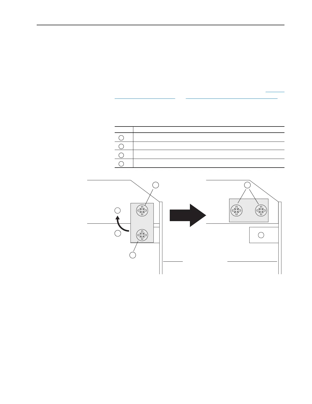
Figure 7.2 Moving Common Mode Capacitor Jumper
Task Description
Loosen upper screw
Remove lower screw
Move jumper to horizontal position
Install and tighten screws
A
B
C
D
Rectifying Circuit Board
A
B
C
D
 Loading...


