EasyManuals Logo

Rockwell Automation Allen-Bradley PowerFlex 700S Installation Manual

Rockwell Automation Allen-Bradley PowerFlex 700S
113 pages
To Next Page IconTo Next Page
To Previous Page IconTo Previous Page
Page #20 background imageLoading...
Page #20 background image
2-2 PowerFlex 700H Control Wiring
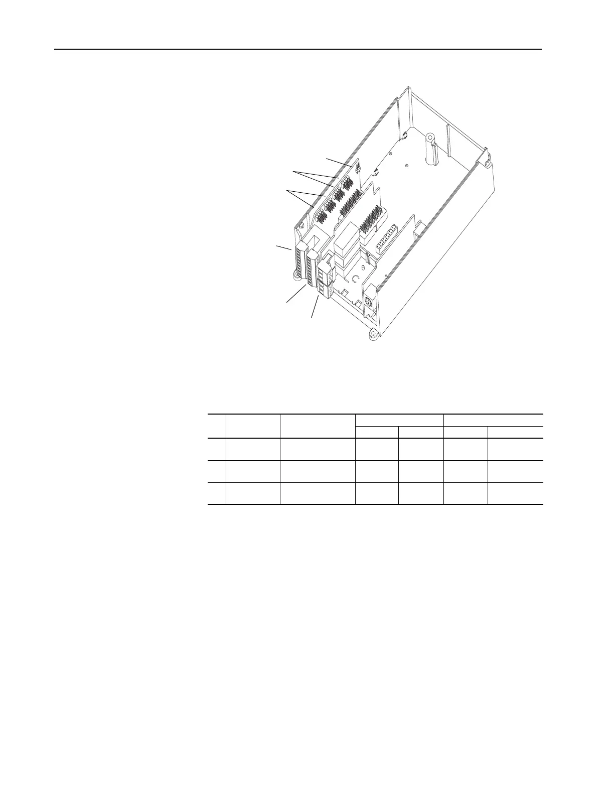
Figure 2.1 PowerFlex 700H I/O Terminal Blocks & Jumpers
I/O Terminal Blocks
Table 2.C I/O Terminal Block Specifications
No. Name Description
Wire Size Range
(1)
(1)
Maximum/minimum that the terminal block will accept - these are not recommendations.
Torque
Maximum Minimum Maximum Recommended
Analog I/O Analog I/O Signals 2.5 mm
2
(14 AWG)
0.5 mm
2
(22 AWG)
0.2 N-m
1.8 lb.-in.
0.2 N-m
1.8 lb.-in.
Digital Inputs Digital Input Signals 2.5 mm
2
(14 AWG)
0.5 mm
2
(22 AWG)
0.2 N-m
1.8 lb.-in.
0.2 N-m
1.8 lb.-in.
Digital Outputs Digital Out Relays 2.5 mm
2
(14 AWG)
0.5 mm
2
(22 AWG)
0.5 N-m
4.5 lb.-in.
0.5 N-m
4.5 lb.-in.
J1 & J2
J3 & J4
J5
I/O Terminal Blocks and Jumpers

Table of Contents

Other manuals for Rockwell Automation Allen-Bradley PowerFlex 700S

Questions and Answers:

Question and Answer IconNeed help?

Do you have a question about the Rockwell Automation Allen-Bradley PowerFlex 700S and is the answer not in the manual?

Rockwell Automation Allen-Bradley PowerFlex 700S Specifications

General IconGeneral
BrandRockwell Automation
ModelAllen-Bradley PowerFlex 700S
CategoryController
LanguageEnglish

Related product manuals